Sidebar
<latex>{\fontsize{16pt}\selectfont \textbf{Dynamic Capability and Trajectory Planning Algorithm Analysis for an Autonomous Construction Site Rover}} </latex>
<latex>{\fontsize{12pt}\selectfont \textbf{[Ali Nouri]}} </latex>
<latex>{\fontsize{10pt}\selectfont \textit{[Master Project RSC]}} </latex>
<latex> {\fontsize{12pt}\selectfont \textbf{Abstract} </latex>
In-situ fabricator (IF) is a mobile heavy-duty robot, which consists of a tracked mobile base and an industrial arm, which is an ABB arm from IRB 4600 series. Actuators of arm are electrical and the base is actuated hydraulically. Primary prototype of IF had four feet but in the present one they are removed. Since the arm is not fixed on the ground unlike the other industrial arms so it can tip over if in trajectory planning of the arm, the stability is not considered. In this thesis the kinematics and ZMP stability criterion for IF is studied. Trajectory generation of arm and cart of IF is done separately and while one is moving the other one is stationary. Two methods for arm and one for cart trajectory planning are presented for producing a stable and fast trajectory to use the whole capacity of the robot without loosing stability. The second method for arm trajectory is simulated in V-REP.
<latex> {\fontsize{12pt}\selectfont \textbf{ZMP} </latex>
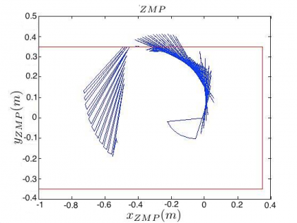
Since in IF the arm is not fixed on the ground, so if in trajectory planning of arm the stability does not take into consideration, the robot will tip over for some trajectories. This simulation shows what will happen if in trajectory planning, we ignore the stability in trajectory planning of IF.
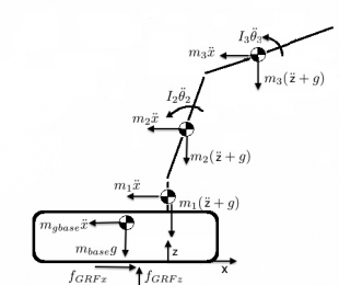
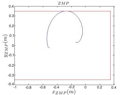
M.Vukobratovic and his colleagues introduced Zero Moment Point (ZMP) concept for stability estimation in 1969 and they improved this criterion later. Zero Moment Point is a point on the ground which the sum of moments of gravity and inertia forces is zero 1).If ZMP stays in support polygon the robot will be stable for the corresponding trajectory. ZMP coordinates are calculated in the following equations: $$ x_{ZMP} = \frac{ \sum_{i} m_{i} x_{i} (\ddot{z}_i+g) - \sum_{i} I_{yi} (\ddot{\theta}_{yi}) - \sum_{i} m_{i} z_{i} (\ddot{x}_i) }{ f_{GRFz} } , i=\{Cart, Base, 1, …, 6\} $$ $$ y_{ZMP} = \frac{ \sum_{i} m_{i} y_{i} (\ddot{z}_i+g) - \sum_{i} I_{xi} (\ddot{\theta}_{xi}) - \sum_{i} m_{i} z_{i} (\ddot{y}_i) }{ f_{GRFz} } , i=\{Cart, Base, 1, …, 6\} $$
<latex> {\fontsize{12pt}\selectfont \textbf{Trajectory Generator for Approach One} </latex>
The inputs of one of the control approaches which is used in IF for trajectory definition, are start and end points, maximum velocity and maximum acceleration of end effector. This method will refine the maximum velocity and acceleration of the end effector for having a stable trajectory.Since the effect of last three joints is negligible in ZMP so the last three joints are assumed rigid to the third link. By inverse dynamic start and end angles of the path can be calculated
 $$ A= \begin{bmatrix}x_{A}
y_{A}
z_{A} \end{bmatrix} \Rightarrow \theta _A = \begin{bmatrix}\theta_{1A}
\theta_{2A}
\theta_{3A} \end{bmatrix} \mbox{if } \alpha=0 $$
$$ B= \begin{bmatrix}x_{B}
y_{B}
z_{B} \end{bmatrix} \Rightarrow \theta _B= \begin{bmatrix}\theta_{1B}
\theta_{2B}
\theta_{3B} \end{bmatrix} \mbox{if } \alpha=1 $$
Using direct interpolation, the trajectory of each joint (first three joints) can be calculated with respect to alpha
$$ \theta(\alpha)= \begin{bmatrix}\theta_{1}(\alpha)
\theta_{2}(\alpha)
\theta_{3}(\alpha) \end{bmatrix} = \begin{bmatrix}\theta_{1A}\times (1- \alpha) + \theta_{1B}\times (\alpha)
\theta_{2A}\times (1- \alpha) + \theta_{2B}\times (\alpha)
\theta_{3A}\times (1- \alpha) + \theta_{3B}\times (\alpha) \end{bmatrix} $$
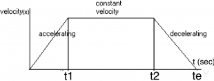
In this control approach the end effector will accelerate and when it reach the maximum velocity, the velocity will be constant and after that end effector will decelerate, so by integrating from velocity function the arc length function of end effector will be calculated with respect to time.
 $$ x(t) =
\left\{
\begin{array}{lll}
\frac{1}{2} a \times t^2                                  & \mbox{if } t \leqslant t_1\\
\\
x(t_1)+  v_{max} \times (t-t_1)          &      \mbox{if } t_1  < t  \leqslant t_2 \\
	\\
 -  \frac{1}{2} a(t - t_2)^2 +  v_{max} \times (t - t_2) + x(t_2)      & \mbox{if }   t_2< t
\end{array}
\right.
$$
The relationship between function of end effector with respect to time and the end effector function, which calculated from forward dynamic, with respect to alpha is
 $$ v_{arc}^2(t)=\frac{dx(\alpha)}{dt}^2+\frac{dy(\alpha)}{dt}^2+\frac{dz(\alpha)}{dt}^2 $$
By solving this equation the function of alpha is calculated with respect to time
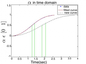
$$ \alpha (t)= \alpha_1 \times t^5 +\alpha_2 \times t^4 +\alpha_3 \times t^3 +\alpha_4 \times t^2 +\alpha_5 \times t^1 +\alpha_6 $$ After ZMP calculation if the trajectory is unstable, by time scaling we can make it stable. In this method the alpha function will be scaled in time and the result will be stable. As it is depicted in the figure the duration of new alpha function is more (slower trajectory).
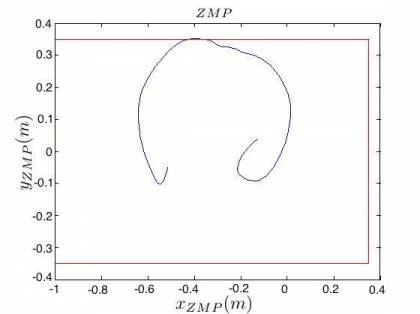
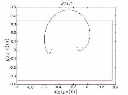
The ZMP profile of old trajectory and the new one are depicted in the following figures. The ZMP profile of the new one (right figure) is completely inside the support polygon, which means it`s stable.
<latex> {\fontsize{12pt}\selectfont \textbf{Trajectory Generator for Approach Two} </latex>
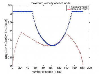 Another approach for controlling IF is to define the trajectory directly for the joint space with respect to time. Using inverse kinematic the start and end angles of each joint will be calculated and in the following steps the corresponding time of each node of trajectory will be calculated. In ZMP calculation the velocity and acceleration of each node is important, so it is impossible to calculate a stable trajectory by finding the maximum velocity of each node without considering the other nodes.
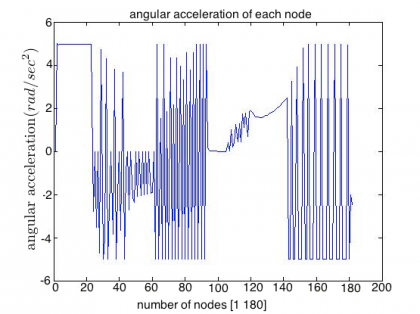
In the first step the maximum stable velocity of each joint will be calculated and it is then by using these upper limits of each node and considering the accelerations the new maximum stable velocity for each node will be calculated. In the figure the blue stars are the primary maximum velocities and the red profile is the new maximum velocities. Since the velocity profile is edgy, the acceleration will change its direction frequently and it is undesirable. The result of this effect is a ZMP profile, which the ZMP will jump from one point to another and it will make the robot unstable. Using moving average the profile will become smooth.
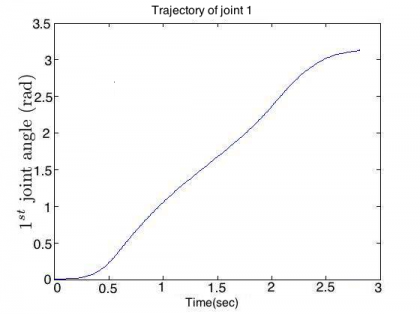
The resultant trajectory and ZMP profile in final step are shown in the following figures.
There was two ways for simulating the trajectory in V_REP. The first one is by position control and the other one is by controlling the velocity directly from callback script. The second one is more reliable since the velocity and position profiles are the same as we calculated but in the first one we do not have access to velocity.
<latex> {\fontsize{12pt}\selectfont \textbf{Trajectory Planning of Mobile Tracked Base} </latex>
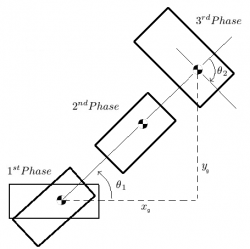 In the chosen trajectory for the cart there are 3 phases. in the first phase it will turn to the goal and in the next phase it will move straight to the goal and when it reached the goal position the last phase start which is taking the orientation. Since in this trajectory the arm is steady during the cart movement so the whole robot can be seen as a rigid body and regardless of the trajectory the limits for velocity and accelerations can be calculated and there is no need to calculate them each time for each trajectory.
| Phase | max vel. ($m/s$) | max $ace. _{ZMP}$ | max $ace. _{structure}$ ($m/sec | 2$) |
|---|---|---|---|---|
| turning | 0.85 | 3.1 | 1 | |
| straight forward | no limit | 10 | 1 | |
| stright backward | no limit | 5 | 1 |
The values, which are calculated in some cases are more than the capacity of the real robot, so the cart is stable for those phases for all values.
<latex> {\fontsize{12pt}\selectfont \textbf{Conclusion} </latex>
For mobile robots, in high-speed trajectories, the stability is also important, and because of the weight of the arm in IF, the inertia forces are high, so they can cause instability. The most used criterion for stability study is ZMP. For trajectory planning of the arm and the cart different methods can be used, which three of them are presented in this thesis. In the first method for arm trajectory planning the maximum velocity and acceleration of end effector are refined for producing a stable trajectory and in the second method, the time corresponding to each node of trajectory is calculated. By comparing the finishing time of each method it is found that in examined scenarios the second method was faster. The output trajectory of other planners can be the input of second approach since this algorithm calculates the corresponding time of each step and so it does not depend on the trajectory. A method is presented for the cart trajectory planning. The arm effects is studied on the ZMP of cart in this phase and it can be used for compensating the ZMP Profile. The effects of the assumptions are studied and it is concluded that because of these simplifications the produced trajectories are not reliable to test on real robot.
<latex> {\fontsize{12pt}\selectfont \textbf{Future Works} </latex>
- Investigating effect of ZMP on friction and ground reaction forces of each track.
- Study the elasticity of the tracks with respect to the ZMP position.
- Identifying the system and the controllers of arm for producing a reliable trajectory.
- Developing these methods for using in an environment with obstacles.

