Sidebar
<latex>{\fontsize{16pt}\selectfont \textbf{Rigid Body Contact Force Solver}} </latex>
<latex>{\fontsize{12pt}\selectfont \textbf{Bolutife Ogunsola}} </latex>
<latex>{\fontsize{10pt}\selectfont \textit{Semester Project, RSC}} </latex>
<latex> {\fontsize{12pt}\selectfont \textbf{Abstract} </latex>
In this project, a hard friction-less contact model as well as an impulse dynamics model for HyQ has been implemented in C++. These models are useful for simulation and trajectory optimization tasks. The models implemented in code depend exclusively on the dynamics library generated by RoboticsCodeGenerator1), as such, this project also presents a template for the implementation of contact/impulse models for other robots for which a dynamics library has been generated using the RoboticsCodeGenerator. Suggestions are presented for future work.
<latex> {\fontsize{12pt}\selectfont \textbf{Overview} </latex>
HyQ is a quadruped robot. Its trunk has 6 DoFs and each of its legs has 3 joint DoFs. As such, HyQ's state (both position/pose and velocity) can be described using a 36 dimensional state vector.
In general the dynamics of a rigid body system is expressible as: \begin{equation} H\ddot{q} + C = \tau + \textcolor{red}{\tau_c} \end{equation} Where:
- $H$ is the joint-space inertia matrix (JSIM)
- $C$ is a vector representing coriolis, centrifugal and gravity terms
- $q$ is the “joint-space” position variable
- $\tau$ is the joint space control input
- $\textcolor{red}{\tau_c}$ is the total joint space “force” corresponding to the total contact forces
The goal of a contact model is to find the contact forces, $\textcolor{red}{\tau_c}$, experienced by the body when there are contact constraints on it. In this project, it is assumed that these contact constraints are possible only on the end-effectors on each of HyQ's legs. For contact on a frictionless surface, where there are no tangential components of the contact forces, $\textcolor{red}{\tau_c}$ can be written as: \begin{equation} \setcounter{equation}{2} \textcolor{red}{\tau_c} = \boldsymbol{T}\boldsymbol{\lambda} \end{equation}
$\boldsymbol{T}$ is referred to as the 'contact jacobian'. It is a mapping from the coefficients of the contact forces, $\boldsymbol{\lambda}$ along the normal direction to the joint-space.
In order to solve for these contact forces, we have to solve the following linear complementary problem (LCP):
\begin{equation}
\setcounter{equation}{3}
\begin{split}
\dot{\boldsymbol{\zeta}} = \boldsymbol{M}\boldsymbol{\lambda} + \boldsymbol{d}
\dot{\boldsymbol{\zeta}} \geq 0
\boldsymbol{\lambda} \geq 0
\dot{\boldsymbol{\zeta}}^T\boldsymbol{\lambda} = 0
\end{split}
\end{equation}
Where:
- $\dot{\boldsymbold{\zeta}}$ is a vector of coefficients of relative velocity between the end-effectors and the contact surface, in the direction of the normal ('separation velocity').
- $\boldsymbol{M} = \boldsymbol{T}^T\boldsymbol{H}^{-1}\boldsymbol{T}$
- $\boldsymbol{d} = \boldsymbol{T}^T\boldsymbol{H}^{-1}( \boldsymbol{\tau} - \boldsymbol{C}) + \dot{\boldsymbol{T}}^T\dot{\boldsymbol{q}}$
Non-negativity of contact forces specifies that a contact surface may push, but never pull. A non-negative separation acceleration while in contact, is required since a negative separation acceleration leads to an immediate violation of contact constraint. Finally, the complementary term specifies that a non-zero contact force implies zero separation acceleration (equivalently, if there is a positive separation velocity, there cannot be any contact force). For a detailed derivation of the LCP, we refer to (Featherstone, 2008)2)
When a collision occurs between one of the end-effectors and a contact surface, there is an instantaneous change in velocity experienced by the whole system. This change in velocity is cause by impulsive forces experienced by the end-effectors during contact gain. The relationship between impulsive forces and change in velocity experienced by end-effectors during contact gain is modeled by:
\begin{equation}
\setcounter{equation}{4}
\begin{bmatrix}\boldsymbol{H} & -\boldsymbol{T}
		\boldsymbol{T}^T & \mathbf{0}
          \end{bmatrix}
          \begin{bmatrix}\dot{\boldsymbol{q}}^{+}\\
          \boldsymbol{\Lambda}\end{bmatrix} =
          \begin{bmatrix}\boldsymbol{H}\dot{\boldsymbol{q}}^-
          \\-e\boldsymbol{T}^T\dot{\boldsymbol{q}}^{-}
          \end{bmatrix}
\end{equation} Where:
- $\dot{\boldsymbol{q}}^{-}$ is the joint-space velocity before a contact gain event.
- $\dot{\boldsymbol{q}}^{+}$ is the joint-spsace velocity after a contact gain event.
- $\boldsymbol{\Lambda}$ is a vector of coefficients of impulsive forces experienced by the end-effectors in contact gain.
- $e$ is the coefficient of restitution for collision between the end-effectors and the contact surface.
This equation is an expression of conservation of momentum (joint-space), including constraints on the direction of the (task-space) velocity of the end-effectors after collision.
<latex> {\fontsize{12pt}\selectfont \textbf{Design} </latex>
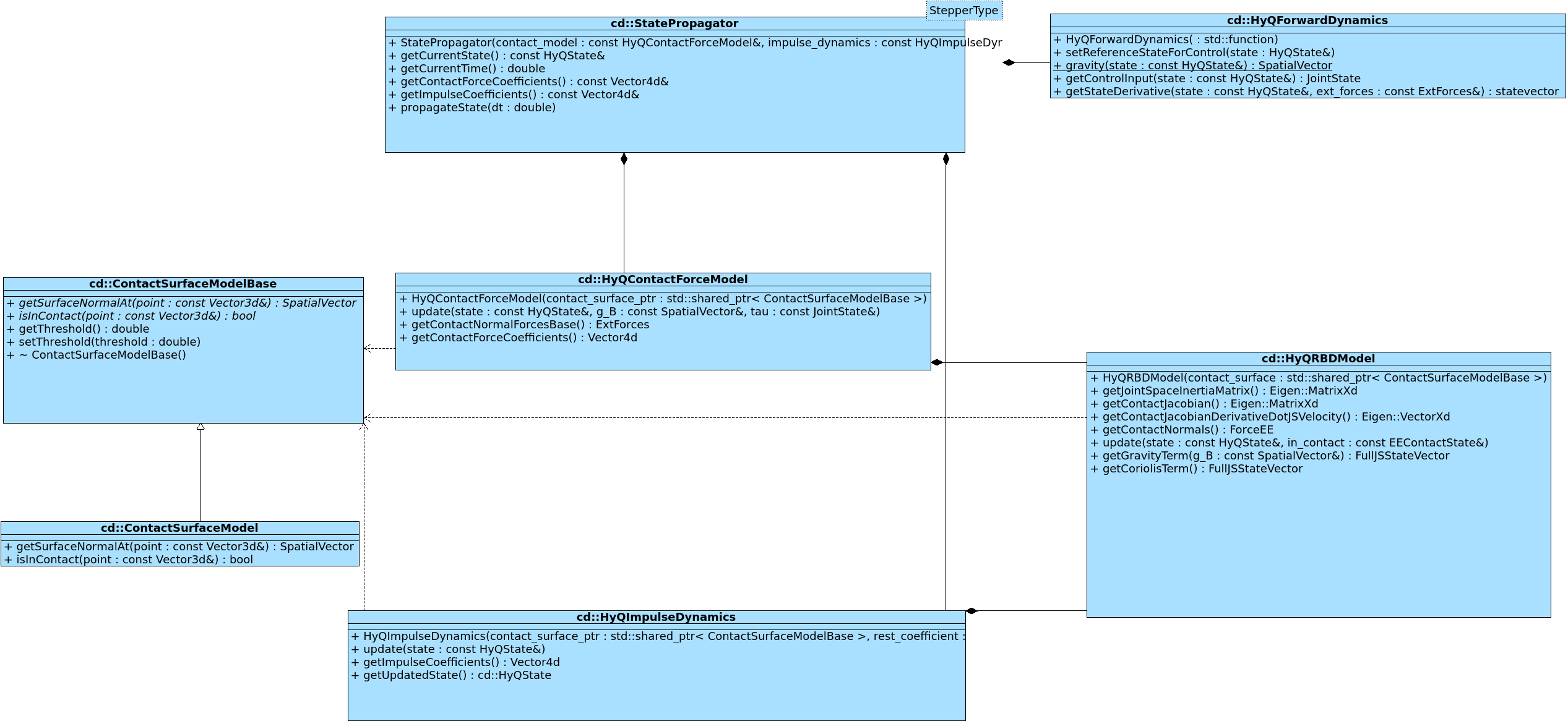
The following is the project's class diagram.
The contact force model is implemented in the class HyQContactModel, HyQImpulseDynamics implements contact dynamics.
ContactSurfaceModelBase is an abstract class that defines an interface for describing a contact surface.
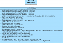
An abstraction over the existing dynamics library that provides the terms required for equations (3) and (4) is provided by HyQRBDModel. HyQState provides a common description of HyQ state, together with related helper functions.
For simulation/visualization of contact dynamics the classes StatePropagator and HyQForwardDynamics are provided. HyQForwardDynamics provides an abstraction over the forward dynamics algorithm available in the dynamics library as well as a method to specify the controller to be used for the simulation task. StatePropagator is an abstraction over boost::odeint3) providing an implementation of simulation with contact dynamics. This class is parameterized over boost::odeint stepper types (that implement various numerical integration schemes).
<latex> {\fontsize{12pt}\selectfont \textbf{Results} </latex>
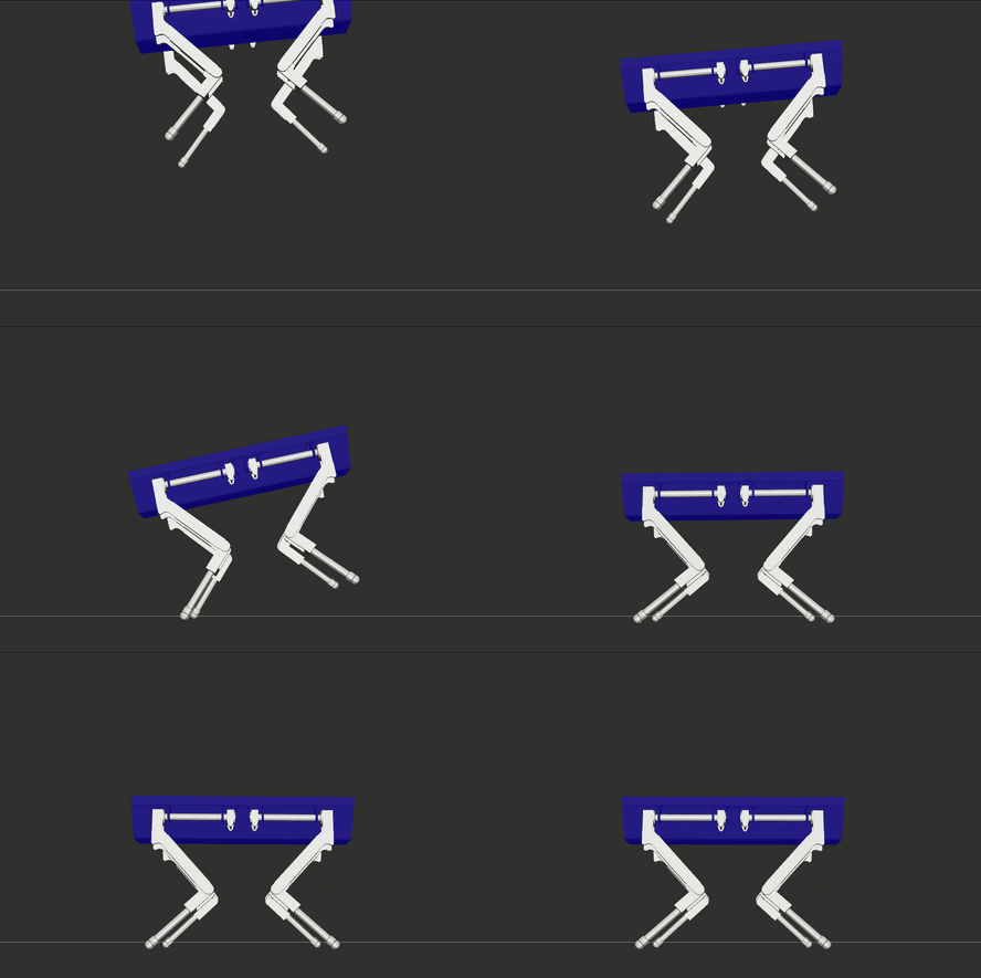
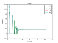
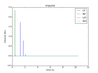
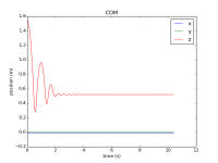
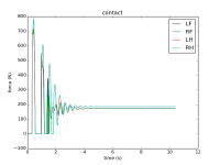
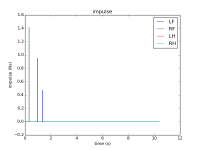
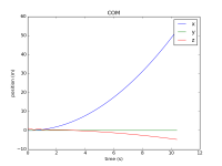
Results for simulation with contact dynamics are shown below for two scenarios. In the first, HyQ is released from an initial position with its feet 1m above ground and its trunk rotated about 5 degrees around the y-axis. In the second scenario HyQ is released from an initial position with its legs 0.5m above a contact surface that is tilted by a rotation of 5 degrees around the y-axis.
| Contact Forces, Impulsive Forces and position of HyQ's center of mass (COM) over time, for scenario 1 |
|---|
| Contact Forces, Impulsive Forces and position of HyQ's center of mass (COM) over time, for scenario 2 |
|---|
The code for both simulations is available in the demo folder of the project repository.
<latex> {\fontsize{12pt}\selectfont \textbf{Conclusion/Further Work} </latex>
In this work hard friction-less contact and impulse dynamics models have been implemented for HyQ. These models have been validated in simulation using different scenarios.
In implementing the contact dynamics models, a set of classes have also been developed in order to facilitate the re-use / extension of these models.
Extension is envisaged in the following directions:
- Code Generation: This project can serve as a template for writing a code generator to generate a contact dynamics library for an arbitrary robot, whose dynamics library has been generated by RoboticsCodeGenerator.
- Contact Generalization: The models can be extended to include friction (i.e. allow for tangential components of contact and impulsive forces) and deformation of contact surfaces. We assume currently that contact is only possible on the end-effectors at the feet. We can extend the models to include contact on arbitrary points on any link of the robot.
- Code Optimization: The contact force LCP (equation (3)), after transformation to an equivalent QP, is solved using a simple QP solver. Exploring different QP solvers as well as techniques like warm starting (between simulation steps), might yield better run-time efficiency of the code.
Another possible code optimization step would be an extensive use of references, including matrix block references, within the code base. This task is well suited with the introduction of machine generated code (since the resulting optimized code might be less readable).
- Integration Generalization: The simulation class
StatePropagatoras is currently implemented supports onlyboost::odeintexplicit stepper types (like euler and runge_kutta4 stepper types).
It can be extended to include support for other odeint stepper concepts. Twoboost::odeintstepper concepts are of particular interest:- Multi-Step Steppers: These steppers improve efficiency by saving a part of the history in order to obtain a higher order method.
- Controlled Steppers: controlled steppers allow for adaptive step sizes determined by an error-estimate. To properly capture possible impact, a sufficiently small step size would have to be used for simulation with a fixed step size stepper. With a controlled stepper, an error-estimate function can be defined such that the step size is reduced only around possible impact events.

