Sidebar
Table of Contents
<latex>{\fontsize{16pt}\selectfont \textbf{Robot-centric auto-calibrating absolute reference system}} </latex>
<latex>{\fontsize{12pt}\selectfont \textbf{[Daniel Schneider]}} </latex>
<latex>{\fontsize{10pt}\selectfont \textit{[Semester Project SE]}} </latex>
Abstract
In this project, the theoretical basis for an implementation of a robot-centric auto-calibrating absolute reference system is presented.
In other words, the position and orientation (pose) of a robot in an absolute reference system (world system) is estimated. In order to achieve that, the velocity of the robot and the states corresponding to a absolute reference system are estimated.
The estimation procedure is done by using an unscented Kalman Filter. The dynamics of the system are modelled using linear acceleration and rotational velocity which is provided by a sensor. The measurements of the system are extracted from camera images provided by a camera on the robot.
Objective
The states concerning the absolute reference system as well as the robots velocity are estimated. This knowledge allows to calculate an accurate estimate for the robots absolute position and orientation.
Setup
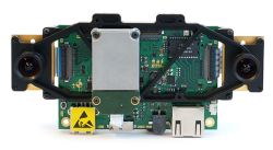
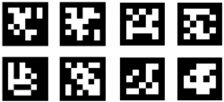
The setup consists out of an autonomous robot equipped with the VI-sensor developed by Skybotix. Furthermore, AprilTags are used as absolute reference markers.
| VI-sensor The VI-sensor records camera images and measures the linear acceleration and the rotational velocity of itself. | AprilTags AprilTags act as visual fiducials (artificial landmarks). They can uniquely be identified. Furthermore, by an adequate camera model (the perspective projection camera model is used) the transformation between the camera and the AprilTags can be calculated. |
Initial Conditions
At the beginning, it is assumed, that only the pose of one particular AprilTag is known accurately. All other poses (poses of all other tags as well as the pose of the robot) are unknown at the beginning.
In addition, it is assumed, that the transformation between the camera and the inertial measurement unit (IMU, the part on the VI-sensor measuring linear acceleration and rotational velocity) is known accurately.
Coordinate systems
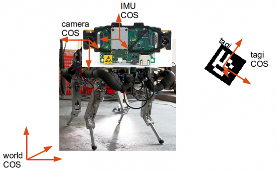
The coordinate systems that are used in the following explanations are shown below.
| COS | Description |
|---|---|
| World | Absolute reference system |
| IMU | COS in which the input is measured |
| Camera | COS aligned with the camera |
| Tag i | COS of tag i, used to refer to the pose of tag i |
States
Due to the goal of estimating the pose of the robot, the state contains the position of the robot and the orientation of the robot. Hence, the states of the system at hand are defined as shown below.
\begin{equation*}
\vec{x}_k =
\left(
\begin{array}{c}
\text{position of IMU in the world COS}
\text{velocity of IMU in the world COS}
\text{orientation of IMU relative to the world COS}
\text{position of tag1 in the world COS}
\text{orientation of tag1 relative to the world COS}
\vdots
\text{position of tagN in the world COS}
\text{orientation of tagN relative to the world COS}
\text{bias of accelerometer}
\text{bias of gyroscope}
\end{array}
\right)}
\end{equation*}
Where N is the number of tags in the system
(Since it is known that the accelerometer and the gyroscope (part of the IMU) each have a bias, but the biases are not known, these biases are included in the states.)
Input and Measurements
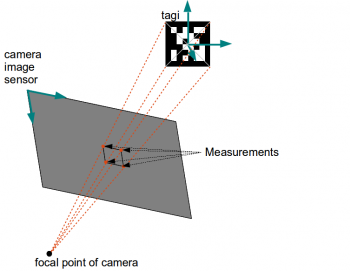
| Input The linear acceleration and the rotational velocity measured by the IMU are considered as input. This is a reasonable definition of inputs since the acceleration and the rotational velocity drive the robot through the world. Using the input, the pose of the robot relative to its initial pose can be estimated. Furthermore the AprilTags are assumed to be stationary, hence their acceleration and rotational speed relative to the world COS is known to be zero. | Measurements The 4 corners of every AprilTag detected on the camera image are considered as the measurements of the system. Hence the measurements are points on the two dimensional camera image sensor (see figure below). The measurements are extracted from the camera images supplied by the VI-sensor. This extraction is accomplished by using the code of the AprilTag library. |
\vec{i}_k =
\left(
\begin{array}{c}
\text{Linear acceleration of IMU in IMU COS}
\text{Rotational velocity of IMU in IMU COS}
\end{array}
\right)
\end{equation*}|\begin{equation*}
\begin{array}{c}
\vec{z}_k
=
(\text{corners of detected tags on camera image})
= (CornersTagsImage)
\end{array}
\end{equation*}|
Results
For the implementation of the state estimation procedure, a model of the system dynamics, a measurement equation and initial conditions are necessary.
| Model of system dynamics The model of the system dynamics consists of a discrete integration of the input. Since the dynamics of the tags is assumed to be stationary, their true and hence also modelled pose do not vary over time. | Measurement equation The measurement equation is derived using a perspective projection camera model. The points on a tag in the 3D space are related to the measurements by a function of the states. |
\begin{array}{c}
\vec{x}_{k+1} = \vec{f}(\vec{x}_k,\vec{i}_k,\vec{v}_k)
\end{array}
\end{equation*}|\begin{equation*}
\begin{array}{c}
\vec{z}_{k} = \vec{g}(\vec{x}_k,\vec{w}_k)
\end{array}
\end{equation*}|
Where $\vec{v}_k$ and $\vec{w}_k$ is noise disturbing the input and the measurements respectively.
Unscented Kalman Filter
The final unscented Kalman Filter procedure distinguishes two cases.
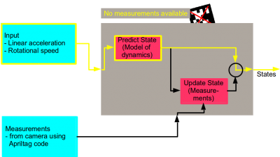
- Case 1 (Prediction): No AprilTag is detected. Hence no measurements are available. The procedure only receives information from the IMU. Using the linear acceleration, the rotational velocity and the model of the system dynamics, the procedure can predict the pose of the robot relative to its initial pose1). Since the dynamics of the tags is assumed to be stationary, their pose stays the same during the prediction phase.
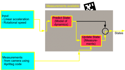
- Case 2 (Update): AprilTag(s) detected
- Case 2.1: Reference tag (tag of which its pose is known accurately) is the/ among the detected tag(s). Using the measurements and the measurement equation, the robot can calculate its absolute pose (position in the world COS). Furthermore, it can calculate all absolute poses of all tags it has detected at least once up to now. Clearly, during the update phase, the IMU data (the input) is still available and used for a more accurate estimation.
- Case 2.2: Reference tag (tag of which its pose is known accurately) is not the/ among the detected tag(s). It is not possible to localize the robot or the tags absolutely. However, the robot still can update its own (already estimated) absolute position and the (already estimated) absolute poses of all other tags it has detected at least once up to now. Clearly, during the update phase, the IMU data (the input) is still available and used for a more accurate estimation.
This procedure is visualized in the following two images.
Architecture of Code
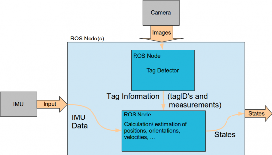
The architecture of the implementation is done using ROS. The process is split up into two sub-processes.
| Tag Detector Detects the tags on the images of the camera and extracts the necessary tag information that is needed for the estimation of the states. This information consists of the tagIDs of the detected tags and the measurements. For this purpose, the AprilTag code was extended with a ROS wrapper. | Filter Estimates the states using the input data and the tag information (tagIDs of detected tags and measurements). A suggestion for the framework for the C++ implementation of the ROS-node containing the estimation procedure was established. |
Outlook
Things that could be improved in the next steps:
- Estimate the transformation between the camera and the IMU. Actually, the transformation between the camera and the IMU is fix due to the construction of the VI-sensor. However, the transformation between these two is not known accurately.
- Up to now, only images of one camera on the VI-sensor are used. To get a more accurate estimation of the states, both cameras could be used.
- The detection of the tags, the identification of their tagIDs and the extraction of the measurements takes most of the time in the estimation procedure. One possibility to reduce the time for the estimation of the states would be to search for tags only in parts of the camera image in which the tags are expected to be.

