Sidebar
<latex>{\fontsize{16pt}\selectfont \textbf{Automating Experimental Archaeology}} </latex>
<latex>{\fontsize{14pt}\selectfont \textbf{KUKA Innovation Award 2015}} </latex>
<latex>{\fontsize{12pt}\selectfont \textbf{Nachiket Dongre}} </latex>
<latex>{\fontsize{10pt}\selectfont \textit{FS2015 Semester project RSC}} </latex>
<latex> {\fontsize{12pt}\selectfont \textbf{Abstract} </latex>
Dexterity in handling various tools marks a clear distinction between humans and animals. Influence of tools and technology on human evolution has been a controversial topic in anthropology. Micro-wear analysis seems like a promising approach, which analyses the traces on lithic remains (i.e. stone tools) generated by the actions of ancient humans. In this method, stone replicas of the original tools undergo known tasks on a known workpiece and thus, a hypothesis is made based on the comparison of characteristics of the traces on the original tool and on the stone replicas. Conclusions on the behavior and lifestyle of early humans can be drawn subsequently. A critical parameter in this method is the quality of traces and the reference stone collection. As of today, human subjects do the task using the replicated stone tools and therefore it is almost impossible to exactly control the critical variables in the task. Thus, use of modern robotic technology can revolutionize this methodology. A force and impedance controlled robotic arm, where all relevant task variables can be precisely set, varied or monitored can effectively replace a human subject performing the task. KUKA LBR iiwa, a highly precise and torque controlled robotic arm is suitable to perform such tasks. Contrary to the human task execution, it shows clear advantages in regards to precision, repeatability and costs. Our approach is based on a task space impedance controller to appropriately mimic anthropomorphic task execution during the contact of tool and workpiece. Further automation has been done in the analysis process, where the precision of the robotic arm is used to automatically focus the tool tip under a light microscope. A novel method for auto-focusing which is based on impedance control mode has also been implemented. Automating the complete process of experimental archaeology facilitates generation of data sets which can be used for statistical comparative analysis.Thus, in this project, a demonstration of the feasibility of robotic-aided Microwear Anaylsis is done. It shows the automation of both the experimental process as well as the microscopic analysis process.
<latex> {\fontsize{12pt}\selectfont \textbf{Micro-Wear Analysis(MWA)} </latex>
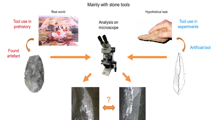
In this approach, firstly, experimental stone tools are created by replicating the original artifacts found at the prehistoric sites. These replicas then undergo known tasks to generate wear patterns. Microscopic traces such as micro-fractures, polishes and striations are formed because of different tasks. The process of MWA is to compare the wear patterns from the original artifacts to those generated on the reference collection. Analysis methods make use of microscopes and methods like laser scanning to record the traces on the tools. However, the major challenge is the experimental part of MWA during which the wear is visible only after a lot of cycles. The experiments are typically carried out by human volunteers. Therefore, having a huge database with a properly controlled critical parameters is unrealistic, especially when the mechanical complexity of the task is taken into account. The analysis process also becomes very cumbersome due to the uneven shape of the stone tools.
The proposed solution is a robotic aided wear tester which can completely automate the existing process. The process is described as follows: After the stone tools are replicated, it is fitted to a robotic arm and employed in a known task on a known workpiece (e.g., using a hafted flake for scraping flesh remainders off a dried sheep hide). The robot can undergo this cyclic task for large number of iterations while controlling the task parameters such as force, velocities, etc.. Analysis process can also be automated by using a precise robotic arm having the capability of automatic focusing. The focused images along with the corresponding data recorded during experimentation can then be stored in a suitable electronic database.
There are several advantages of this approach as given below:
- Precision and Control: Robots are capable of executing tasks precisely up to their designated limits. During each execution, the robot can be programmed to precisely monitor and control sensitive parameters like working angle, velocity, force and torque.
- Repeatability: A large number of cycles have to be undertaken for the wear experiments that are performed on soft materials like animal hides. Robots can maintain their performance over a long term owing to the high repeatability.
- Cost efficiency: In order to have a large reference collection, a lot of experiments need to be conducted using paid and reliable human volunteers which can become expensive and time consuming.
- Automated analysis: The traces are generated on a plane which is at a certain angle on the tool tip. The robot can navigate the tool at any point on the tool tip precisely and focus it. Automatic focusing helps to generate sharp and high resolution images of the traces. Efficient image processing algorithms can then be designed to compare the generated traces with the original ones.
Complete Experimental and Analysis Setup
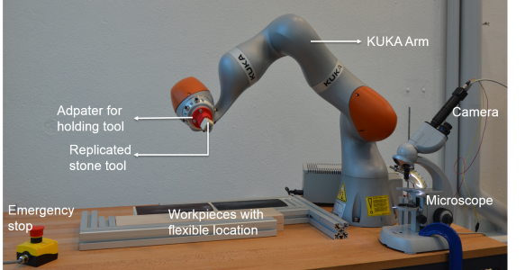
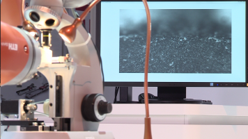
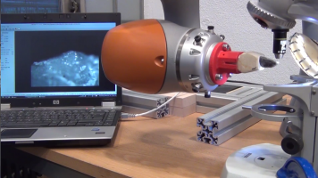
Figure shows the complete experimental setup of the Robotic aided micro wear analysis task. The tool was attached to the robot using a 3d printed adapter. The mounting for the workpieces is flexible so that position of the workpiece can be changed as needed. The microscope with an attached camera is kept next to the robot for automated analysis task. The proximity of the microscope to the robot increases the repeatability of the end-effector position during microscopy. Emergency stop should be used in case of any problem with the system.
<latex> {\fontsize{12pt}\selectfont \textbf{Tasks} </latex>
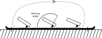
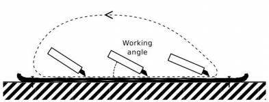
- Scraping and Whittling: The motion of the scraping tasks is shown in the figure. The distinguishing property for scraping and whittling is the working angle relative to the direction of motion.
- Sawing: A sawing task can be implemented for tools which exhibit a rather long edge. It is basically a workpiece undergoing a typical to and fro sawing motion using the stone replicated tool.
Controlled Parameters: The force in Z-direction needs to be controlled since it determines the level of scraping that the workpiece undergoes. Also, if the force is too high, it can damage the workpiece and if its too low it will take too long to generate the traces. The speed with which the tool scratches the surface in contact phase can have significant effect on the generation on wear. Also the working angle determines the orientation of the tool with respect to the workpiece.
Impedance Control
There are two inbuilt control modes for the given KUKA arm: Position control and impedance control. In the implementation of our tasks, the tool is in contact with surface. Therefore, control of force at the end effector is essential. This can be implemented by using the impedance control mode of the KUKA arm. Under impedance control, the robot's behavior is compliant. It is sensitive and can react to external influences such as obstacles or process forces. The application of external forces can cause the robot to leave the planned path. The underlying model is based on virtual springs and dampers, which are stretched out due to the difference between the currently measured and the specified position of the tool tip. The characteristics of the springs are described by stiffness values, and those of the dampers are described by damping values. These parameters can be set individually for every translational and rotational dimension.
Tool path programming
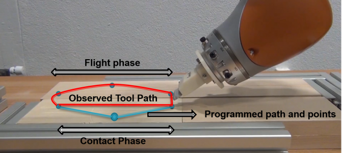
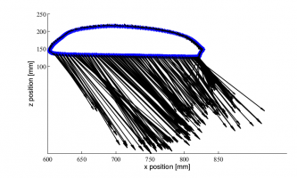
Figure shows the tool path of the typical path of a scraping task and different phases of the path. Such a path can be programmed by assigning specific points through which the tool should pass. Also, inbuilt functions are used to define parameters such as the type of motion, velocity, acceleration. The transition between two points can also be defined to obtain a smooth motion.
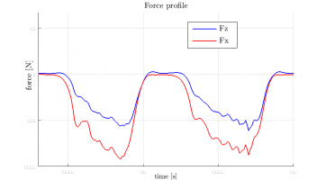
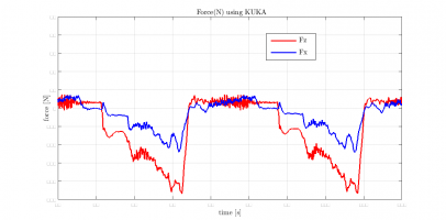
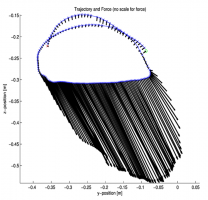
For all the tasks, it is imperative to use the Cartesian Impedance control mode during the contact phase. During the flight phase, either pure position control or impedance control can be used. For transitions from the flight phase to contact phase, the tool is in impedance control as well. The set point of the tool is programmed to be under the surface at a particular distance as per the force required. Starting at a position slightly above the workpiece, the tool moves downwards with a low velocity and stops the motion when the desired force value is reached. The stroke is then executed by moving the set point in horizontal direction. The set point can be moved in vertical direction as per the desired force profile during the task. Stiffness parameters were set to low values to reduce to effect of varying ground height on the resulting force. Stiffness values in x-y directions as well as in orientations were set to rather high values to keep deviations of the respective set points low. Damping values were set to 0.8 to reduce the oscillations of the end effector during contact. Singularities in the flight phase can be avoided by varying the orientation during the flight phase and then again keeping it constant during the contact phase to generate a proper plane of traces. Thus, any desired force profile can be generated by setting appropriate points and motions types in the contact phase of the path. A force profile similar to that generated by a human can be obtained as shown in the figure by setting appropriate points in the path during the contact phase of the task. The profiles in the task done by the robot have an irregular appearance since the workpiece used was a hard material.
<latex> {\fontsize{12pt}\selectfont \textbf{Microscopy} </latex>
The process of analysis is also automated to provide continuous experimentation and faster generation of datasets. The process shown in the figure is sketched as follows: The robot executes the task for given number of cycles. After that robot moves the tool below the microscope at lowest speed possible. After the tool tip is positioned under the objective, the robot automatically focuses the tip. Manually controlled movement of the tool tip under the microscope is also possible to view the area of interest and capture the real time images. After the images are taken, the robot moves back to area of workpiece and starts the next interval.
Focus Measure
The most critical part of this process is finding the focus of the images due to the low depth of focus for high magnification objectives. Also, a measure is needed to quantify the focus of an image. There are several methods prescribed in the literature to find out the focus measure of an image, e.g, Image Contrast, DCT Energy measure, Grey-level local variance, and Gaussian Derivative. Out of these, the measure obtained using Gaussian derivative based method gave the best and robust results and is described below.This method says that the measurement of the focus score can best be based on the energy content of a linearly filtered image. It can be deduced that an optimal focus score is the output by the gradient filter.
$$\[F(\sigma)=\frac{1}{NM} * \sum_{x,y} [f(x,y)*G_x(x,y,\sigma)]^2 + [f(x,y)*G_y(x,y,\sigma)]^2 \]$$
where $\(F(\sigma)\)$ is the focus measure, $\(f(x,y)\)$ is the image gray value, $\(NM\)$ is the total amount of pixels and $\(G_x, G_y\)$ are the first order Gaussian derivatives in x and y directions.
This formula was implemented in MATLAB to calculate the focus measure of the incoming images and the value of the measure is sent back to the JAVA application using the JAVA-MATLAB interface as described earlier.
<latex> {\fontsize{12pt}\selectfont \textbf{Autofocus} </latex>
Autofocus is essential for fast completion of the analysis procedure and also to locate the areas on the tool which are of interest. The tool can be focused automatically using the KUKA arm either in position control or also in impedance control mode. The mechanisms to focus, however are different for both the modes which are described in the following section.
Autofocus using position control
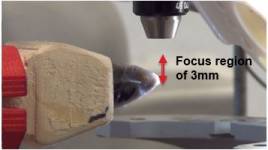
A closed loop feedback controller is developed to automatically focus the tool. For automatic focusing, the tool always has to be in the focus region as shown in figure. Also the robot is set to move with 0.1 mm at each step. The objective is to maximize the relative focus measure obtained. The given focus measure is maximum at the focal plane. Therefore, let $x$ be our state variable and $u$ be the input, then $\(x \epsilon \big[ 0,3 \big]\)$, $\(u \epsilon \big\{ -0.1,0.1 \big\} \)$ and the system equation becomes $$\( x(k+1) = x(k) + u(k) \)$$ at time step $k$.
Control Strategy
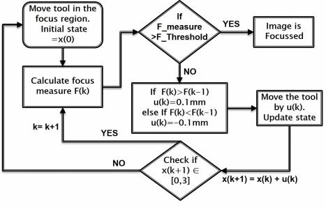
The closed loop control is graphically explained in the flowchart below. The initial state of the tool which is inside the focus region is fixed and hard coded in the program. Then the focus measure $F(k)$ is calculated. If the focus measure is above a certain threshold, then the image is focused. This threshold was found by experimentation. If it is not above the threshold then the focus measure at the previous time step is checked. If the measure at earlier step is lesser than current measure, that means we are heading in the right direction and a positive input should be given. Otherwise, a negative input is given. After moving the tool, the state of the system is updated and checked if it is within the domain. If it belongs to domain then the cycle is repeated. If not, then it goes back to the initial position and starts over. After the image is focused, it can be checked by going one step ahead if the focus measure is maximum or not. It was typically found that the obtained focus measure by thresholding was the maximum that could be achieved with a precision of 0.1mm.
One interesting point to note here is that even if the robot is configured to directly reach the focus point once we find it, the tool tip won't be focused and so, autofocus would still be needed. This is because there is always some error in exactly finding the location of tool tip due to the irregular shape of these tools. Therefore, the actual tool tip will be a few millimeters away from the programmed tool tip. Also the tool tip location will change due to the wear generated during the task. Therefore, autofocus becomes an important requirement of this application.
Autofocus using impedance control
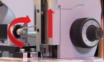
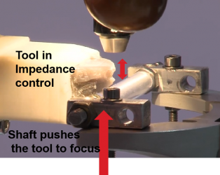
Autofocusing via position control of the robot has a precision of 0.1mm. This precision is quite low compared to the microscopic level. There might be certain points or areas of interest on the tool which we might not be able to focus with that method. In that case, a stepper motor can be used which has a much higher precision to accurately focus. In this approach, the stepper is connected to the microscope knob, which moves the platform of the microscope. The robot is set in an impedance control mode with low stiffness. The virtual set point of the tool tip is set lower than the platform location. This makes the tool rest on the platform such that its spring loaded virtually. Then each step of the motor will cause a small movement of the tool. Thus, using similar control strategy as described above focus can be achieved. Figure shows the setup of the stepper controlling tool motion.
 <latex> {\fontsize{12pt}\selectfont \textbf{Preliminary Results} </latex>
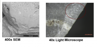
Several experiments were done using the setup described earlier and the figure below shows some of the initial results. The difference between the traces available and those generated by robot will help to invent efficient algorithms to generate similar patterns. Image analysis and interpretation was not a part of this project but remains as future work.
<latex> {\fontsize{12pt}\selectfont \textbf{Hannover Messe 2015} </latex>
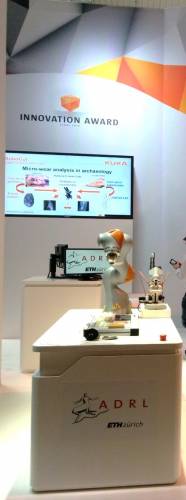
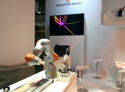
This project was proposed for the KUKA Innovation award 2015. The KUKA LBR iiwa was provided by KUKA AG as a sponsored track agreement for the duration of the competition. The working video of the application programmed was submitted to the jury of the KUKA innovation award on 15th February 2015 based on which, this project was selected into the finals. The finals were at the Hannover Messe 2015 from 13th to 17th of April at Hannover in Germany. Therefore, a short demonstration was programmed which showed the complete experimentation and analysis process in about two minutes. Also, there were some changes in the setup for the Hannover Messe and therefore fine tuning of the parameters in the code had to be done to make the demonstration. The project was presented to the public as well as to other industry professionals.

