Sidebar
<latex>{\fontsize{15pt}\selectfont \textbf{Programming and Design of Control Methods for Human Interaction with a Ballbot}} </latex>
<latex>{\fontsize{12pt}\selectfont \textbf{Fotios Fotou}} </latex>
<latex>{\fontsize{10pt}\selectfont \textit{Semester Project RSC}} </latex>
<latex> {\fontsize{12pt}\selectfont \textbf{Abstract} </latex>
The aim of this semester project is to design and implement control methods on a ballbot, Rezero, in order to be able to balance carrying different weight loads. To fulfill this goal an adaptive controller is designed for the ballbot. The controller consists of a parameter estimator, which estimates the inertia parameters of the system, the ballbot and the weights, and a controller gain adaptation mechanism. The adaptation procedure and the parameter estimation should be implemented on an embedded control system, as a result a new computationally more powerful microcontroller board is used for the fast controlling algorithm. The board is programmed in order to communicate with the other electronics of the robot, the sensors and the high level PC, and operate at its maximum potential.
<latex> {\fontsize{12pt}\selectfont \textbf{The Microcontroller Board} </latex>
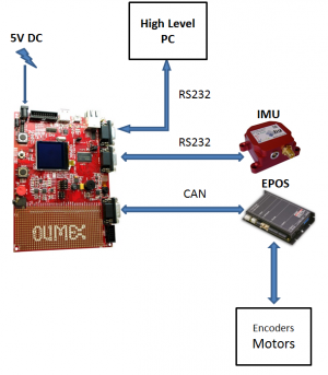
On the microcontroller board is implemented the controller, which is absolutely essential in order for the ballbot to balance at the upright position. The board gathers data from the sensors, computes the controller actions and feeds them to the power electronics, which in turn control the motors of the ballbot. In addition, it takes reference commands from the high level PC and gives to it the sensor data and the controller output for storage.
 The board is the STM32-P407 board from Olimex and has the STM32F407ZGT6 microcontroller from ST Microelectronics. The microcontroller has an ARM Cortex M4 CPU and a floating point unit and its clock runs at up to 168MHz.
The clock frequency is set to its maximum value and the communication interfaces between the microcontroller and the other electronics of the ballbot are developed. As it is shown in the picture above the microcontroller communicates with the IMU and the High level PC using RS232 protocol and with the power electronics (EPOS) using CAN protocol. The specifications of the communication protocols, ie the bitrate, number of data bits, format of the data packets etc, were defined in the bachelor thesis “Regelung eines auf einem Ball balancierenden Roboters” of Samuel Schueller and Swen Wigert. This semester project is about programming the board in order to build the interfaces and meet these specifications.
During the development of the interfaces taking full advantage of the board's capabilities was the main goal. For example the Direct Memory Access Controller(DMA) is used to conduct data transfers between the microcontroller's memory and USART peripherals without the CPU involvement saving this way computing power for other tasks. The USART (Universal Synchronous Asynchronous Receiver Transmitter)peripheral transmits and receives data serially and is necesary for the RS232 interface.
<latex> {\fontsize{12pt}\selectfont \textbf{The Adaptive Controller} </latex>
An adaptive controller is proposed in order for the ballbot to adapt to different weight loads and balance at the upright position.
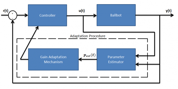
 The adaptive controller consists of the parameter estimator and the gain adaptation mechanism.
- Parameter Estimator
The parameter estimator takes the system inputs -forces and torques- and outputs -tilting angles,position and velocities- and estimates the system's inertial parameters that are changing when additional weights are put on the ballbot, mass, center of gravity and moments of inertia. The estimator is from Atkeson et al (1986) “Estimation of Inertial Parameters of Rigid Body Links of Manipulators”.
- Gain Adaptation Mechanism
This mechanism computes the gain of the Linear Quadratic Regulator of the linearized around zero system with inertial parameters, the estimated ones.Each time the controller gain has been computed, a new gain is calculated by taking the new parameter estimates.
The adaptive controller has not yet been tested in simulation nor on the real system.
<latex> {\fontsize{12pt}\selectfont \textbf{Future Work} </latex>
- Complete the board code in order for the ballbot to balance using the new board. At this moment, the interfaces between the board and the electronics are built, but they need further testing and to be put together in one project.
- Test the estimation procedure in simulation until the estimated parameter values are close to the real ones. At this point, the estimation results are not good, but the cause might be the approximation of the system's dynamics that is considered. As a result, the first step should be to verify the dynamics approximation and then validate the estimation algorithm using this approximation.
- Test the adaptive controller both in simulation and on the real system.

