Sidebar
<latex>{\fontsize{16pt}\selectfont \textbf{Development of an Arm Control Strategy for an In-Situ Fabricator}} </latex>
<latex>{\fontsize{12pt}\selectfont \textbf{[Fotios Fotou]}} </latex>
<latex>{\fontsize{10pt}\selectfont \textit{[Master Project RSC]}} </latex>
<latex> {\fontsize{12pt}\selectfont \textbf{Abstract} </latex>
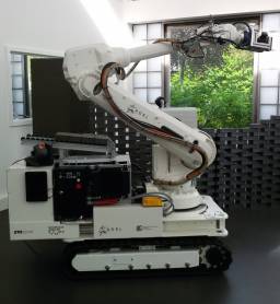 An In-Situ Fabricator or IF is a heavy duty robot that is being developed as advanced platform for mobile manipulation with the long-term goal of autonomously performing tasks on construction sites. Our IF consists of an industrial robot arm mounted on a tracked base. In order to take full advantage of the arm's potential, thus making the whole robot more dexterous, the arm control strategy should be modified. A method of controlling the arm by position streaming is developed, exploiting the capabilities of the arm's controller. On a Linux based controller, a path planning scheme is designed in ROS, which generates a trajectory for the arm, as well as a server, which streams this trajectory point by point to the arm controller. The path planning scheme is based on MoveIt!, software for mobile manipulation. In addition, software is developed for the arm controller in the RAPID programming language. A communication interface is implemented between the Linux based controller and the arm industrial controller based on the option Robot Reference Interface, which provides a stable data exchange at a high rate. The performance of the IF arm using the position streaming idea is, then, evaluated.
<latex> {\fontsize{12pt}\selectfont \textbf{The Arm Control System} </latex>
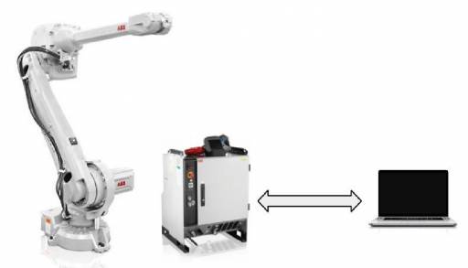
Our In-Situ Fabricator is composed by a mobile base and an industrial robotic arm. The arm is the ABB IRB 4600-40/2.55 and it is controlled by the ABB IRC5 controller. The controller moves the arm based on commands received by a PC via a network connection. The main components of the arm control system are shown in the figure below.
<latex> {\fontsize{12pt}\selectfont \textbf{Motivation for the New Arm Control Strategy} </latex>
The arm has great capabilities; it can achieve great speeds and accelerations. For example, it can move from one side to the other, rotating around its axis 1, which is the axis perpendicular to its base in approximately 1 second, as this joint’s maximum speed is $175^o/s$. In addition, it is designed, so it can operate mounted on the floor, on the ceiling or even tilted in an industrial environment. If the arm is mounted on a rigid and steady surface, as in an industrial application, a trajectory is planned and stored in the arm controller, which the arm follows and probably repeats, depending on the application. However, mounted on top of the mobile base, the arm's capabilities can not be fully exploited, as the robot's base tilts, when the arm moves. Furthermore, we need to design our own collision checking algorithms, as well as study advanced motion planning algorithms and control techniques that are not included in the ABB software. Consequently, a new control strategy has to be designed, with which a trajectory can be computed online on a controller, other than the arm controller, in order to compensate for the tilt of the base increasing the robot's performance and ensuring safety.
<latex> {\fontsize{12pt}\selectfont \textbf{The Arm Control Strategy} </latex>
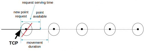
The developed strategy is called position streaming. According to this strategy, the arm's trajectory is computed from a PC and it is streamed to the arm controller point by point. Then, the arm controller moves the arm to each trajectory point based on the settings sent with the point. The procedure of moving the arm is the following. The controller moves the arm to a waypoint. When the tip of the arm, called Tool Center Point (TCP), reaches the waypoint at a specified distance, the waypoint is considered executed. Then, without stopping the motion, the controller sends a request to the PC for a new point and starts moving towards the next waypoint stored in a buffer. At some point, during the movement the controller receives the new waypoint and stores it in the buffer. Consequently, there should be at least two points in the buffer always, in order for the arm to move continuously. The time from requesting a new point to the time instant when the point is available in the buffer is called Request Serving Time, and it should be less than the movement duration for the motion to be continuous.
<latex> {\fontsize{12pt}\selectfont \textbf{Arm Controller Software} </latex>
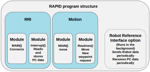 The controller is programmed using the high-level programming language RAPID. The controller software is called RobotWare; ABB provides software options and the ability to create user software components. The most important RobotWare options used are the Multitasking option and the Robot Reference Interface (RRI) option. Using the Multitasking option, the user is able to divide an arm's application into smaller parts, called tasks. Each task consists of modules, which contain the Main and other routines. The RRI option supports a stable and high-rate data exchange up to 250Hz between the controller and the PC; the communication is based on this option. The software structure of the developed controller software is shown in the figure. There is a task, called RRI, which initializes the RRI option and connects to a server on the PC. Each time a message is received, an interrupt is triggered and the data are stored. Then, the Motion task, which contains the motion instructions, moves the arm according to the commands sent by the PC. The RRI runs in the background collecting and sending the arm data to the PC and receiving the PC messages periodically.
<latex> {\fontsize{12pt}\selectfont \textbf{PC Software} </latex>
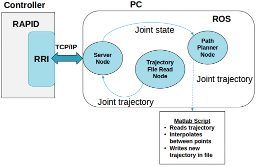 The PC software is implemented in the Robot Operating System (ROS), this way already available software for mobile manipulation can be utilized and more features can be later included more easily. Furthermore, the code for controlling the arm can be incorporated in the high-level controller of the IF, described in 1) Our goal was to implement the position streaming idea and plan and stream a trajectory to the controller point by point. A path planner is designed based on the software MoveIt!. MoveIt! provides a lot of plugins to useful libraries such as Open Motion Planning Library, which was used for planning the arm trajectory. The main advantage of MoveIt! is that the user provides the planning settings such as the robot description, constraints, velocity and acceleration limits and MoveIt! configures the planner. However, this posed our main limitation too. To our knowledge, the user is not able to configure directly the planner, for example, for selecting the resolution of the trajectory in space. In addition, the user can not initialize the planner with a specific trajectory, which essential for a replanning scheme. To overcome the inability to define the time spacing of the points and due to limitation in time, matlab is used, in order to interpolate in time between the points of the trajectory computed by the MoveIt! based Path Planner node. Then, the trajectory is read from a file from another ROS node and sent to the Server node. The Server node streams the trajectory to the controller, when a waypoint is requested.
<latex> {\fontsize{12pt}\selectfont \textbf{Experiments} </latex>
<latex> {\fontsize{10pt}\selectfont \textbf{Robot Reference Interface} </latex>
The data exchange between the arm controller and the PC is tested by exchanging messages. The highest data exchange rate supported by the RRI is achieved, 250Hz. In addition, it is observed that the performance of the communication is influenced by the RAPID program of the controller.
<latex> {\fontsize{10pt}\selectfont \textbf{Comparison of the RRI based communication with previous works} </latex>
The RRI based communication is compared with the communication method used in previous works, which is called Socket-Based communication. The difference between the two methods is that using the latter method, data exchange on the controller side is not handled by the RRI, but it is handled by user created network sockets and routines. The measure of comparison is the Request Serving Time, which pose a limit to the minimum movement duration, which in turn limits the maximum velocity and the maximum space resolution of the trajectory. A trajectory created by the Path Planner node is sent and executed three times using each communication method and the Request Serving Time is measured for each waypoint request. The results prove that the RRI communication provides a lower maximum value of the Request Serving Time. The results are shown in the table.
| Request Serving Time | |||
|---|---|---|---|
| Socket based | RRI(250Hz) | ||
| Mean(ms) | Max(ms) | Mean(ms) | Max(ms) |
| 24.5 | 32 | 9.4 | 14 |
<latex> {\fontsize{10pt}\selectfont \textbf{Arm Performance} </latex>
A series of experiments are conducted, in order to verify that the lower limit on the movement duration is posed by the Request Serving Time. A trajectory is planned and the time spacing between the points is selected. Then, the trajectory is streamed to the controller using the RRI and executed and the arm motion is observed. After that, a new trajectory with smaller time spacing is computed and the experiment is repeated. The time spacing is reduced at each repetition, until the arm motion is not continuous anymore. It is observed that the RAPID program influences the motion of the arm more than the communication, as the motion of the arm is not continuous for waypoint time spacing greater than the limit posed by the Request Serving Time. Trying to reduce even more the time spacing results in a “move and stop” motion, while no communication problems are observed.
<latex> {\fontsize{12pt}\selectfont \textbf{Conclusion} </latex>
A communication interface between the arm controller and the PC is developed using the RRI. The highest data exchange rate of 250Hz provided by the RRI is achieved. Software is designed for the arm controller and the PC, in order to be able to plan a trajectory for the arm and execute it. In addition, the MoveIt! software adequacy for our application is evaluated. Finally, experiments are conducted, which revealed the limitations of the arm controller.
<latex> {\fontsize{12pt}\selectfont \textbf{Future Work} </latex>
- Modify the path planner, in order to be able to configure the waypoint spacing of the trajectory in time and space.
- Optimize the RAPID program, in order to decrease the waypoint time spacing of a trajectory that the arm can execute, thus increasing the effective control frequency
- Investigate further how the arm controller and the ABB software influence the movement of the arm. Examine how the acceleration settings influence the arm motion.

