Sidebar
<latex>{\fontsize{16pt}\selectfont \textbf{Modelling and Control of the Hydraulic Drive System of an In-Situ Fabricator}} </latex>
<latex>{\fontsize{12pt}\selectfont \textbf{Edo Jelavić}} </latex>
<latex>{\fontsize{10pt}\selectfont \textit{Semester Project, EE}} </latex>
<latex> {\fontsize{12pt}\selectfont \textbf{Abstract} </latex>
In this thesis the control for hydraulic drive train of In-Situ Fabricator robot class is being developed. Dynamic model of the system is obtained using the white box modelling approach and measurements are conducted to identify some of the system's parameters. In order to achieve track velocity control, appropriate control structure is chosen and controllers are tuned. Developed control algorithms are tested on the robot. Additionally, a method for velocity estimation based on pressure and flow measurements is investigated. Guidelines for possible future work are given.
<latex> {\fontsize{12pt}\selectfont \textbf{Goal} </latex>
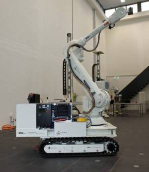 ADRL is developing robot of a class In-Situ Fabricator (IF) for autonomous construction tasks directly on building construction sites. Robot is shown in Figure on the right. To complete the construction task, the robot must be able to position itself in desired place. Therefore, it is desirable to develop control strategies for robot track velocities.
<latex> {\fontsize{12pt}\selectfont \textbf{System Overview} </latex>
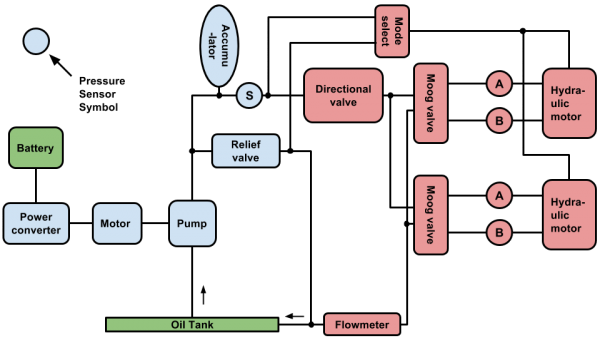
IF's drive train consists of two main sections: pressure supply unit and propulsion unit. The pressure supply unit produces pressure in the system by pumping in oil from the tank. This pressure is then being used by the propulsion unit to generate movement (i.e. move the robot tracks). Such partition of the system has been made in order to alleviate design of the control algorithm. In Figure below, simplified scheme of the system is depicted.
Figure above shows parts of the system which were of most importance for developing dynamic model. Parts colored in blue constitute pressure supply unit, parts colored in red constitute propulsion unit and parts colored in green are not significant for modelling, but without them Figure wouldn't make much sense. Black lines represent hoses.
<latex> {\fontsize{12pt}\selectfont \textbf{System Modelling} </latex>
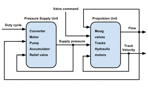
To describe the system, a white-box modelling approach is adopted. This means that the system model is in a form of differential equations which describe underlying physical processes; as much as possible <latex>{\textit{a priori}} </latex> information about the system is used. However, since one does not have absolute knowledge about the system, some of the model parameters had to be identified. System schematic with interactions between pressure supply unit and propulsion unit is shown in Figure below. This is foundation of the model.
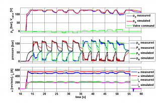
To compare behavior of the model with one of the real system, system had been pressurized and then step commands to the valves have been sent. Comparison of key quantities is shown below. These include pressures and flow estimation.
<latex> {\fontsize{12pt}\selectfont \textbf{Control System Design} </latex>
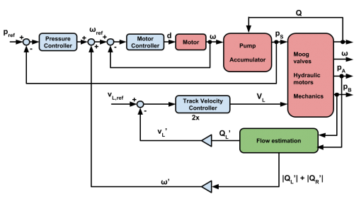
The control system has been split into two parts: supply pressure control loop and track velocity control loop. The diagram outlining structure of the control system is shown in Figure below.
Components constituting the system are shown in red color, components of the control system are in blue color and estimator is in green color. Control system comprises out of the pressure control loop, which should provide constant supply pressure for the propulsion unit, and two track velocity control loops (one for each track). Pressure control loop also uses a feed-forward control; knowledge about disturbances that act on the system is used here to improve performance. In total, the system has three inputs: desired supply pressure and desired track velocities for two tracks. Mark “2x” indicates that there are two instances of the track velocity controller. Subscript “L” tells that it is the left track which is being shown here.
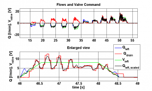
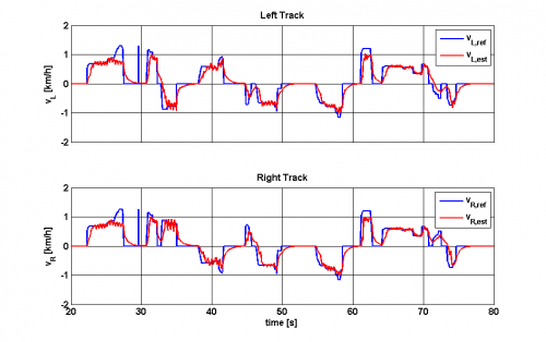
The goal set in the introduction has been achieved. Flow estimation is used to close the track velocity control loop. Robot movement is smooth and predictable. Velocity tracking is shown in Figure below.
<latex> {\fontsize{12pt}\selectfont \textbf{Conclusion} </latex>
In this work modelling and control system development for an IF has been done. To model the system white box approach has been used. This approach has one nice feature; complete insight and understanding of physical processes in the system, as well as understanding of interactions between components. This is nice because one can choose how complex the model should be and which effects are to be neglected. Also, the model can be expanded and its complexity can be increased without too much effort. This would not be possible with a black-box model (identification process would have to be done all over again). However, the downside of this approach is that some of the parameters are not listed in specification sheets and it is difficult to identify them. This was the major difficulty during this work. Identifying parameters was a problem because it was impossible to isolate one component (parameter) and do the identification. This is in general the case with hydraulic systems. In this particular case additional problem was that the system had been assembled previously and there was no hope of working with any component separately. After obtaining the model, control system was designed. It has been done using the information from the model. Controllers have been designed in frequency domain and tuned using a MATLAB control toolbox. Although the model isn't perfect representation of the real system, it captures the dominant dynamics and model-based tuning gave decent results. There are also few limitations in the hardware which put an upper bound on performance that one may expect from the system. Ultimately, the goal set at the beginning of this work seems to be achieved. The verb “seems” has been used here because there are some scenarios (fast driving, driving on the inclination) which the author was not able to test for practical reasons.

