Sidebar
<latex>{\fontsize{16pt}\selectfont \textbf{Closed-Lo\nobreak\hspace{.001em}op Positioning of Large-Scale Robotic Systems}} </latex>
<latex>{\fontsize{12pt}\selectfont \textbf{[Lukas Stadelmann]}} </latex>
<latex>{\fontsize{10pt}\selectfont \textit{[Master Project ME]}} </latex>
<latex> {\fontsize{12pt}\selectfont \textbf{Introduction} </latex>
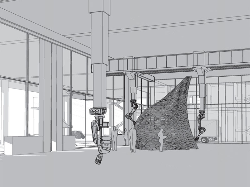
The Robotic Fabrication Laboratory (RFL) is part of the new building for the Institute of Technology in Architecture (ITA) located at the ETH Zürich. It allows research in the field of large-scale robotic fabrication for many different disciplines due to its versatile design. Four six-axis ABB industrial arm robots are mounted upside-down to a gantry system running under the ceiling of the RFL. This allows movement of the robots in a large volume of 43 x 16 x 8 meters. 1)
The installed robots feature very precise positioning of the end-effector relative to their robot bases. In this setup, the robot bases are tracked using encoders on the different axes of the gantry system. Therefore, elastic deformations and oscillations of the gantry system and even of the whole building result in a low accuracy for positioning the end-effectors of the mounted robots.
In order to increase the accuracy it is planned to do closed-loop position control of the robot end-effectors. The states of the robots will be measured using the large-scale position tracking system Nikon iGPS. For sending reference trajectories to the robots the new Externally Guided Motion (EGM) interface from ABB will be used.
This thesis aims to set up and test all the required components to do closed-loop control in the RFL.
<latex> {\fontsize{12pt}\selectfont \textbf{Externally Guided Motion (EGM) Interface} </latex>
Externally Guided Motion (EGM) is a new interface from ABB to control their robots on a low-level. It is faster than the other available interfaces since this one by-passes the path planning. Getting feedback about the state of the robot and sending position and speed references to the robot is provided with a frequency of 250 Hz. EGM shows a pure time delay of around 25 ms. The references can be specified using joint or pose mode. This interface requires a stream of sent position and speed references that is as smooth as possible. The sent trajectory has to take care of the maximum joint torques otherwise EGM will run the robot into dynamic overloads.
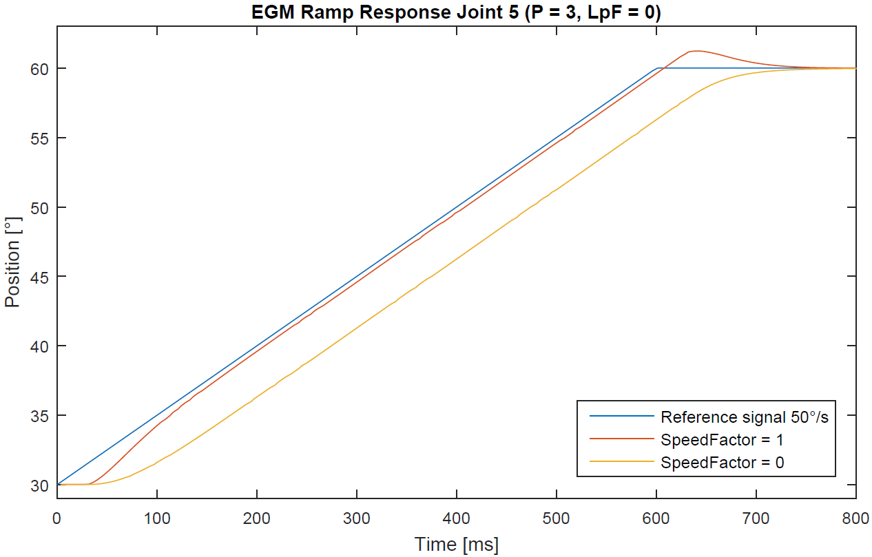
A parameter tuning and performance tests were carried out. The three most important parameters of the EGM-Interface are the PosCorrGain (P), the LpFilter (LpF) and the SpeedFactor (SF). Generally, the position correction gain (P) influences the responsiveness of the movement towards the target position and the factor low-pass filter (LpF) can be used in case of an unsmooth reference trajectory. The figure on the left depicts the influence of the SpeedFactor which is simply a factor applied to the speed reference signal. It can be seen, that with the SpeedFactor set to one the robot tries to catch up the reference signal after the pure time delay. However, at the end it overshoots the final value. The SpeedFactor can be chosen arbitrarily between zero and one. This allows to tune for any behavior in-between the two shown lines.
A ROS C++ software package was created that integrates all the EGM functionalities. The source code and detailed explanation about how to use it can be found in the repository EGM-Interface 2).
<latex> {\fontsize{12pt}\selectfont \textbf{iGPS System} </latex>
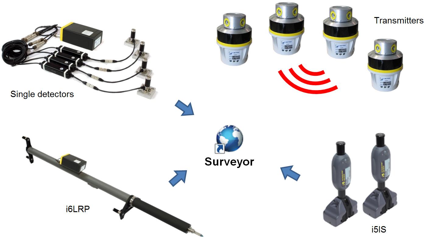
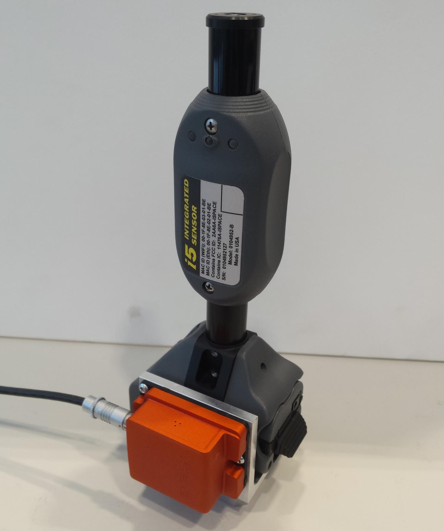
The fundamental components of the iGPS 3) system are depicted in the figure on the right. There is a set of transmitters which emit infrared laser pulses that can be received by the detectors. Depending on the time differences of these pulses the positions of the detectors are determined. Multiple detectors combined build up a frame which will be tracked by the main software Surveyor. Several measuring probes are available such as the i6 Long Reach Probe (i6LRP) and the i5 Integrated Sensor (i5IS). The i6LRP features six detectors, which provides tracking of a six degree of freedom frame. There is as well a tip that allows measuring single points. The i5IS consists of two detectors and offers therefore a five degree of freedom frame. This probe is a compact unit with all the necessary electronics integrated. Several i5IS can be combined to build up a six degree of freedom frame.
Surveyor buffers up the received pulses in a queue to allow interpolation of the pulse data and increase the robustness due to network latencies. This way, it is possible to output an update of the frame positions at a constant rate of 40 Hz.
Performance tests of the iGPS system showed that it provides high-quality position measurements with sub-millimeter precision if it is well calibrated, offers good visibility and the transmitter locations are arranged optimally. However, the system shows a delay of about 250 ms in outputting the data, originating from the pulse buffer.
To make the iGPS data available for a broad range of applications, a software package was created which publishes it to ROS topics. Detailed explanations and
the source code can be found in the repository iGPS-Interface 4).
<latex> {\fontsize{12pt}\selectfont \textbf{i5 Pendulum Just iGPS} </latex>
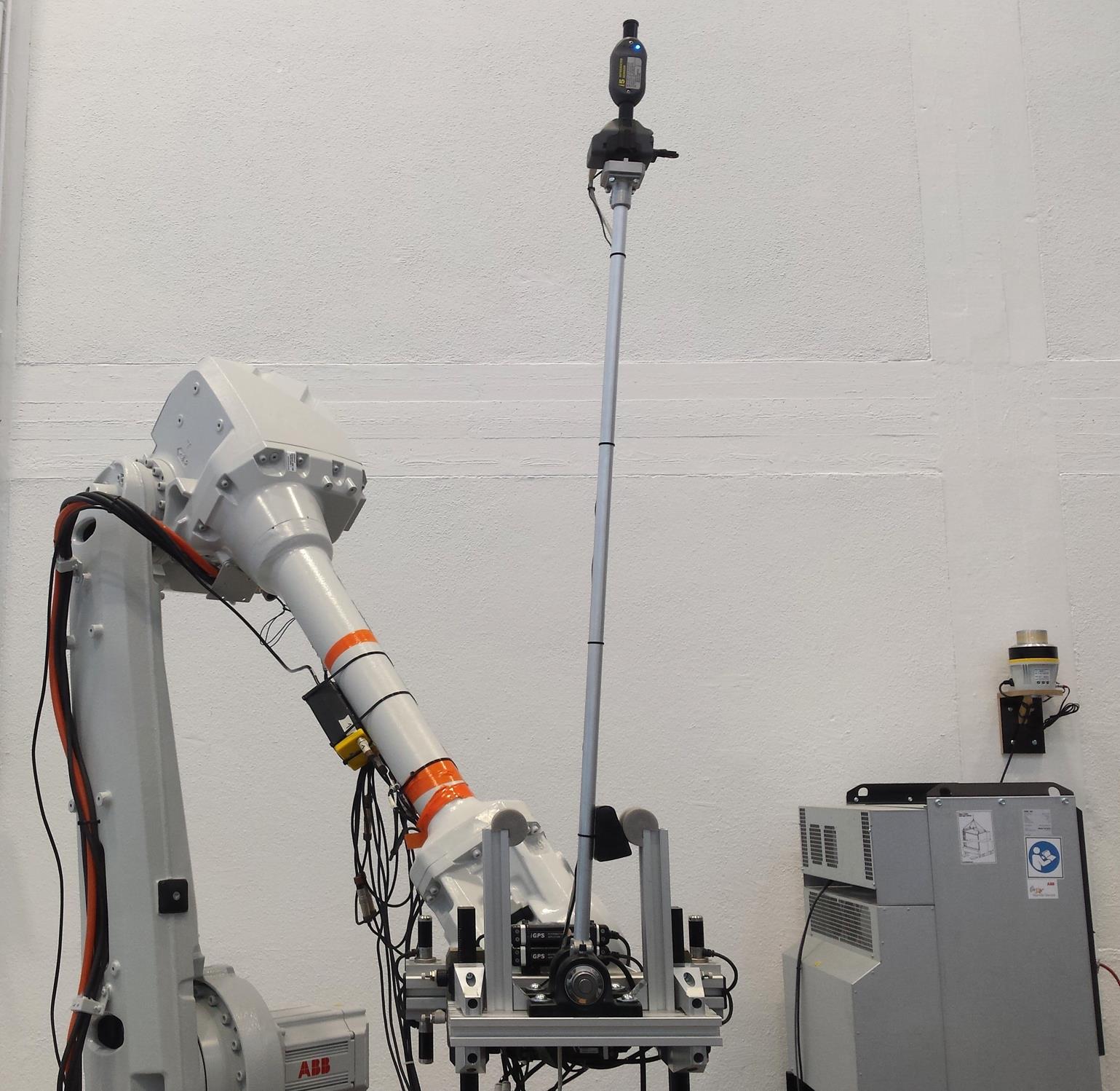
Due to the fact that during this thesis the RFL still was under construction, no robot with a moving base was available. However, an ABB IRB 4600-40/2.55 robot with a fixed base could be used. Since it is pointless to track the fixed base, closed-loop control using iGPS and EGM was tested on an inverted pendulum setup which can be seen in the figure on the left. At the top of a lightweight aluminum pole an i5 probe was placed. The angle φ is measured using the i5 orientation and the position x is measured using the EGM feedback of the robot. This way, both can be tested.
A Matlab Simulink simulation of the pendulum was created. Since the robot is assumed to be really fast its dynamics was not modeled. The acceleration of the x-axis is controlled, integrated and then send to the robot as position and speed reference.
An LQG controller was added to the simulation and the maximum possible measurement delays were investigated. It was possible to stabilize the pendulum in a reasonable amount of time and an acceptable range on the x-axis up to a measurement delay of 150 ms with a pendulum length $l$ of one meter. iGPS Surveyor offers the possibility to adjust the length of the pulse buffer queue. On this setup, with just one i5, it was possible to decrease the length to 100 ms while still providing robust output. Furthermore, the output of the iGPS system was forward integrated by another 50 ms using the recent velocities. The tuning of the LQG controller parameters started in simulation and was then finished on the real pendulum.
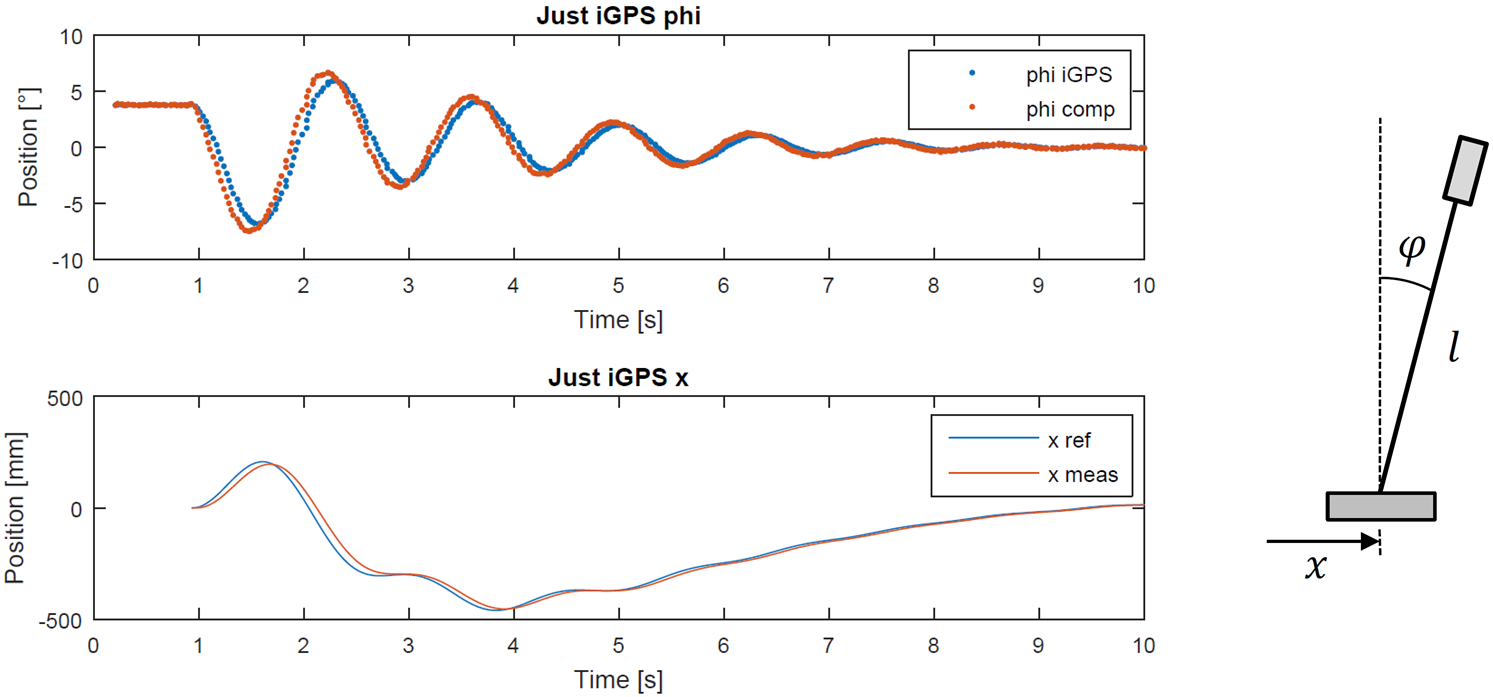
The figure above presents the performance of the pendulum recovering from an initial position of 3.8°. The upper plot shows the φ-angle extracted from the raw iGPS data represented by the blue dots. The red dots show the forward integrated angles using the recent velocities. It can be seen that the delay is compensated by approximately 50 ms. However, applying this method a relatively big overshoot is induced. The x-position is depicted in the lower plot. It shows the reference position sent to the robot and the feedback position received from the robot.
Generally, the pendulum requires a considerable amount of time and quite a bit of space on both axes to get back to the desired zero position. Further tests showed, that recovering from initial positions larger than 7° were not possible. The pendulum did not offer high robustness. Disturbing it using a long stick was just possible with slight pushes otherwise it required too much space along the x-axis and left the range of the robot. The delay until the pendulum reacted to the disturbances was quite big and clearly visible by eye.
<latex> {\fontsize{12pt}\selectfont \textbf{i5 State Estimation} </latex>
To increase the performance of closed-loop control using the iGPS system the decision was made to fuse it with an IMU. As a test setup the i5-IMU assembly depicted in the figure on the right was developed. It combines an iGPS i5 probe with an MTi-100 IMU from Xsens.
Fusing the data allows to get rid of the large delay of iGPS due to the low delay output of the IMU. The rate of outputting new measurements will be increased to the IMU frequency of 400 Hz. Short visibility losses, outliers or bad quality measurements will no longer lead to performance failures of the closed-loop control since the IMU with its more consistent data transmission, much higher frequency and robust output will take care of that. The dependency on the inconsistent data communication to Surveyor will be decreased. Instead of just assuming the most recently received measurement to be corresponding to the actual current state, the iGPS timestamps of the measurements will be used.
The i5 State Estimation code was created in collaboration with Timothy Sandy, PhD student at the ADRL. His batch estimation code, based on 5), was adapted to work with the i5-IMU assembly.
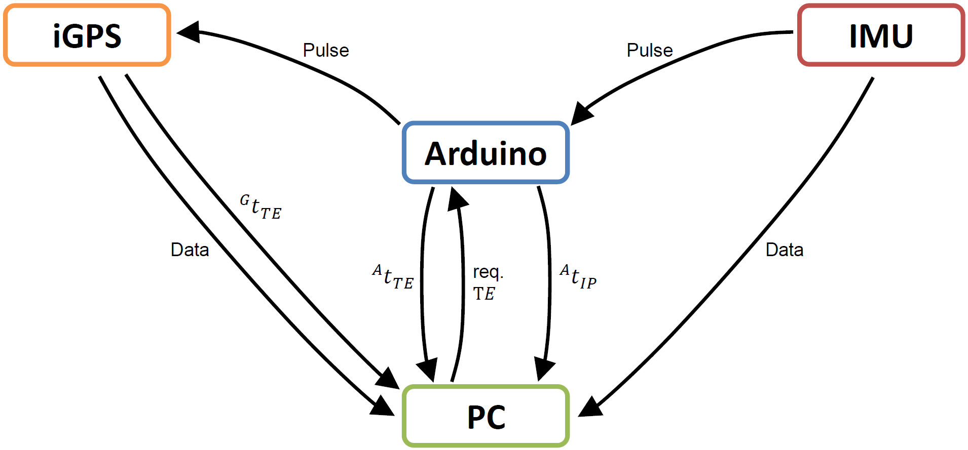
A crucial requirement to be able to fuse the iGPS data with the IMU data is to have the output of the two systems synchronized. The figure on the left presents the procedure used to convert the timestamps of the iGPS and IMU data to the Arduino time frame. The computer handles the data streams from the IMU and the iGPS system and the Arduino is used to handle the fast low-level communication by sending and receiving pulses.
The procedure starts with the computer requesting a timestamp event from the Arduino which then transfers a Pulse to the iGPS system. After that, the Arduino sends the time when it triggered the timestamp event in its own time frame $^{A}t_{TE}$ back to the computer. When the iGPS system receives the pulse from the Arduino a timestamp event is generated which's time expressed in iGPS time frame $^{G}t_{TE}$ is passed to the computer. Using the timestamps $^{A}t_{TE}$ and $^{G}t_{TE}$ the computer can update a TICSync mapper 6) which allows converting in-between the two time frames. Timestamp events, and therefore updates of the mapper, are triggered with a frequency of 1 Hz. Parallel to that, the timestamps of the iGPS data packets received by the computer are converted to the Arduino time frame using the current mapping parameters.
The synchronization procedure for the timestamps of the IMU data is based on 7). On this setup, the IMU sends pulses along with every fifth data packet. The Arduino transfers the time when it received the IMU pulse expressed in its own time frame $^{A}t_{IP}$ to the computer. The computer then matches the time $^{A}t_{IP}$ to the timestamp of the corresponding data packet from the IMU and updates a TICSync mapper, using those two timestamps, which enables the conversion in-between the two time frames. Parallel to that, the timestamps of the data packets from the IMU are mapped to the Arduino time frame using the current mapping parameters.
In order to test the accuracy of the iGPS/ IMU Synchronization the i5-IMU assembly was hit by hand. Comparing the output of the iGPS system to the output of the IMU during the hit resulted in a time offset of the synchronization of 1-4 ms.
The source code of the created software can be found in the repositories MSc_thesis_LStadelmann 8) and in if_pose_est 9) on the branch i5_pose_est.
<latex> {\fontsize{12pt}\selectfont \textbf{i5 Pendulum With IMU} </latex>
For testing the performance of closed-loop control using the EGM interface and the iGPS system fused with the IMU, the i5 on top of the pendulum was replaced with the i5-IMU assembly and all the necessary hardware for the iGPS/IMU synchronization was installed. The angle φ of the pendulum is measured using the output of the i5 State Estimation. Otherwise, the control strategy is the same. The length of the pulse buffer queue from Surveyor was set back to the default value of 200 ms. This way, the full iGPS delay has to be compensated. The controller was retuned starting in simulation and finishing on the real pendulum.
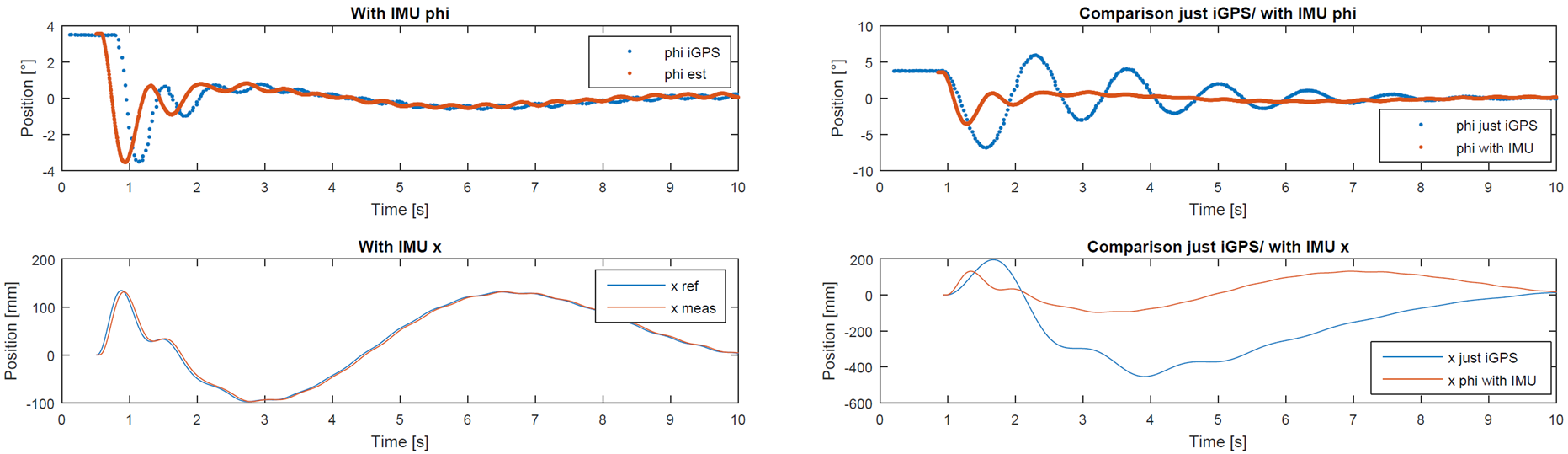
The figure on the left shows the performance of the pendulum recovering from an initial position of 3.8°. In the upper plot, the blue dots represent the angle φ extracted from the raw iGPS data of the orientation from the i5. The red dots show the angle φ determined by the output of the i5 State Estimation. It is clearly visible that the red dots feature a lot higher frequency and that the two measurement signals of the angle φ are shifted in time by approximately 230 ms.
The pendulum requires roughly 1.5 s to stabilize the angle φ. Here, recovering from initial positions up to 12° was possible. Disturbing the pendulum using a long stick worked with quite big pushes while keeping the angle φ close to zero and not using a lot of space along the x-axis. There was no visible delay between the hit and the pendulum reacting to that disturbance.
The performance of the pendulum that just uses the iGPS can now be compared to the pendulum which uses the iGPS data fused with the IMU. The figure on the right shows the comparison for recovering from the same initial position of 3.8°. Using the fused data to measure the angle φ results in a lot quicker behavior. Much less space and time is needed to get the pendulum back to the desired zero position. Recovering from higher initial positions is possible and the robustness is significantly increased.
<latex> {\fontsize{12pt}\selectfont \textbf{Conclusion and Outlook} </latex>
This thesis aimed to set up and test all the necessary components which allow closed-loop position control of the robot end-effectors in the RFL. The states of the robots are measured using the large-scale position tracking system iGPS and the reference trajectories are sent to the robots using the new Externally Guided Motion (EGM) interface from ABB. Both systems were set up and their performance was investigated. C++ software packages, including detailed explanations, were created which allow interfacing EGM and iGPS from the Robot Operating System (ROS).
The behavior of closed-loop control using iGPS and EGM was evaluated on an inverted pendulum setup. Due to the large time delay of iGPS the performance was unsatisfactory. Hence, it was decided to fuse the iGPS data with an IMU to compensate for the delay, increase the frequency and improve the robustness. In order to do that, a synchronization method was developed which converts the data from the iGPS system and the IMU to the same time frame. This made it possible to implement a state estimation algorithm which fuses the data together.
The inverted pendulum setup was adjusted to work with the output of the state estimation, which enabled testing the performance of closed-loop control using the EGM interface and the data from the iGPS system fused with an IMU.
Therefore, the foundation for closed-loop control in the RFL is provided. As next steps, the dynamics of the gantry system combined with the robots has to be investigated. Depending on the results, a control strategy can be developed. The system then may be implemented in the RFL which enables closed-loop control of the robot end-effectors. Further steps include the creation of high-level interfaces, such as a connection to Rhinoceros (CAD software used in architecture), which allow easy control of the robots.
Page Tools
