Sidebar
<latex>{\fontsize{16pt}\selectfont \textbf{Improving force control on a hydraulic quadruped}} </latex>
<latex>{\fontsize{12pt}\selectfont \textbf{[Manuel Koch]}} </latex>
<latex>{\fontsize{10pt}\selectfont \textit{[Semester thesis, ME]}} </latex>
<latex> {\fontsize{12pt}\selectfont \textbf{Abstract} </latex>
In legged robotics, compliance control has become one of the most prevalent methods to deal with unplanned physical perturbations. While HyQ has been shown to be one of the best performing robots in this field, further improvement was the objective of this thesis. Experimental evaluation has shown unsatisfactory force tracking, particularly during the flight phase of the leg. This is mostly caused by the low weight of the HyQ legs, especially the lower limb, which leads to low inertia and therefore fast system dynamics. Additionally, the low weight in combination with high noise amplitudes on the force sensors in the joints leads to low force/noise ratios. In the scope of this project, oversampling of the force sensors was implemented, which allowed for better noise suppression, using a higher order filter without increasing the delays. An appropriate filter was selected and run on HyQ. A reduction of the standard deviation of the force tracking error on the knee joint during flight phase by up to 50% compared to the current system was achieved.
<latex> {\fontsize{12pt}\selectfont \textbf{Motivation and Idea} </latex>
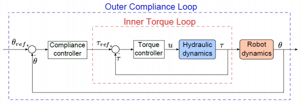
A legged robot, especially when intended for use in heavy terrain, has to be able to deal with unexpected obstacles and perturbations while moving. Such uncertainties cannot be handles using simple position control. Impedance controllers with an outer position control loop and an inner force control loop have to provide the necessary compliance for smooth movements under rough conditions. The process of the inner force control loop is referred to as force tracking. The figure below shows the general layout of such a control scheme (Picture by Thiago Boaventura):
Experiments with HyQ have shown insufficient force tracking performance, especially during the flight phase of the leg. There are two main reasons for this. Firstly, the low weight of the HyQ leg in combination with the powerful hydraulic actuation system create fast system dynamics, i.e. it gives the control system little time to align actual and desired force. Secondly, the high noise amplitudes in combination with the low weight of the leg lead to a low signal-to-noise ratio.
| This figure shows the tracking of a $1 Hz$ sinusoidal reference force (blue) during flight phase on one of the knee joints on HyQ in its current configuration. It can be seen that almost no force tracking takes place. The low signal-to-noise ratio can also be seen on in the force measurements (blue). |
The idea to improve force tracking was to implement oversampling of the critical force sensors, which allows to use a higher order filter without increasing the filter delays, which can be highly critical for an agile legged robot. A better measuring performance would allow higher gains in the force control without causing instabilities, which should improve the force tracking performance.
<latex> {\fontsize{12pt}\selectfont \textbf{Software concept} </latex>
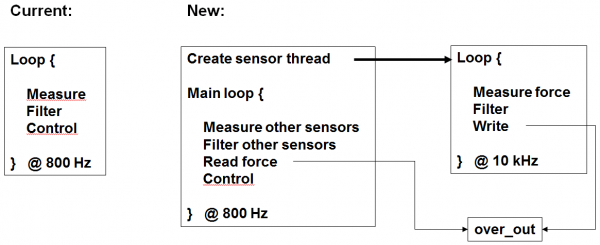
The figure below shows a graphical comparison of the current software concept for the control and the new one that was implemented as part of this project.
In the current system, reading and filtering all sensor signals as well as the whole control system are run at $800 Hz$.
In order to enable oversampling of the force sensors, an additional thread is created, in which the force sensor signals are read, filtered and written to a global variable $over\_out$. As shown in the figure below, the desired frequency for oversampling the force sensors is $10 kHz$. In the main loop, the non-force sensor signals are measured and filtered as it was in the current system. Additionally, the filtered force values are read out from the global variable $over\_out$. The control part and the frequency of the main loop remain as they were.
<latex> {\fontsize{12pt}\selectfont \textbf{Filter selection} </latex>
A variety of digital filters were evaluated. Among them FIR filters such as moving average and IIR filters such as Butterworth, Chebyshev 1 & 2 and elliptic filters. All having their respective advantages and disadvantages, two filters were selected for further testing: Moving average filters of different lengths and Butterworth filters of different orders. While in theory Chebyshev and elliptic filters may offer equally good performance, they would have required a full implementation from scratch in C++, which may have clashed with the limited time frame available. Butterworth filtering on the other hand was already implemented on HyQ and moving average filters are by far the easiest to write from scratch.
| This figure shows the step responses of a 10 element moving average filter and Butterworth filters with orders from 1 to 4 with a cut-off frequency of $500 Hz$ at a sampling frequency of $10 kHz$. A slow step response for the 1st order Butterworth can be seen. The higher order Butterworths show delay, overshoot and ringing that is increasing with the order. The moving average shows a rather quick step response while being inherently free of overshoot and ringing. Since noise reduction measurements have yielded almost identical results for all filters (except 1st order Butterworth, which performed worse), the moving average is the obvious choice for for final implementation. | 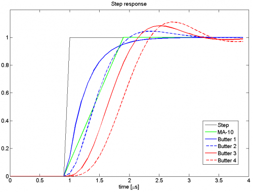 |
<latex> {\fontsize{12pt}\selectfont \textbf{Results} </latex>
Ultimately, the desired oversampling frequency of $10 kHz$ was not reached. The results shown below were obtained with an oversampling frequency of $5600 Hz$. Since the control frequency is $800 Hz$ and it was desired that the filter delay does not exceed one control time step, the length of the moving average was set to 7 elements.
| This figure shows a zoom into a force peak of a test of the filter performance, during which the respective joint was moved up and down by hand. The graph shows the raw (blue) and filtered (green) measurements. For comparison, the raw data was reduced to $800 Hz$ and processed through an emulation of the original Butterworth filter. It can be seen that the new moving average filter smoothes the noise well and reacts significantly quicker than the original filter with the lower sampling frequency. | 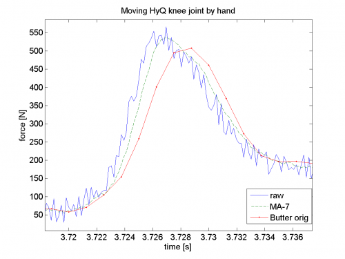 |
| This figure shows a comparison of the force tracking error on a knee joint during flight phase between the current system (NOS) and the newly implemented oversampling (OS) with adapted gains. The error is defined as the difference between the reference value and the filtered measured value. This experiment was conducted with different reference trajectories and additional loads on the leg. The standard deviation of the force tracking error was consistently reduced by 40-50% in all configurations. |
<latex> {\fontsize{12pt}\selectfont \textbf{Conclusions} </latex>
Two major conclusions can be drawn from this project. Firstly, oversampling of the force sensors on the knee and hip joints of HyQ with adapted filtering is a functional method for improving force tracking performance. Even with multiple optimization steps pending, the standard deviation of the force tracking could be significantly decreased. Secondly, a moving average filter is well suited for the emerging filtering task. The conducted evaluation actually suggest that the moving average filter matches or outperforms the commonly used Matlab-designed Butterworth filters of different orders in terms of quick reaction to input steps and noise reduction.
<latex> {\fontsize{12pt}\selectfont \textbf{Future work} </latex>
Multiple steps could be taken to further raise the oversampling frequency and force tracking performance:
- The driver of the DAQ board currently seems to be a limiting factor. Performance could be significantly increased by an adapted scheduling that requires less channel switches.
- The task of measuring and filtering could be outsourced to four embedded microcontrollers, i.e. one for each leg. This way extremely high sampling frequencies could be achieved and scheduling issues on the main computer could be decreased.
- The current main computer of HyQ appears to be rather slow. If available, a faster model could speed everything up.
- The analog filter is still specified for the current system. It may eventually be adapted to the new Nyquist frequency.
Once these steps are implemented and a final oversampling frequency is established, the digital filter will of course require new tuning.
Page Tools
