Sidebar
<latex>{\fontsize{16pt}\selectfont \textbf{Global and local state estimation of the In-Situ Fabricator while building mesh mold}} </latex>
<latex>{\fontsize{12pt}\selectfont \textbf{Manuel Lussi}} </latex>
<latex>{\fontsize{10pt}\selectfont \textit{Master Thesis, RSC}} </latex>
<latex> {\fontsize{12pt}\selectfont \textbf{Abstract} </latex>
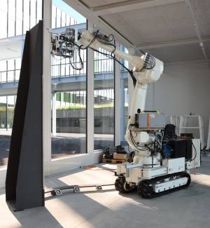
 The In-Situ Fabricator (IF) was designed for autonomous fabrication tasks such as building the mold of a user-defined, undulated wall based on a mesh-structured composition of small steel wires. Even though the robot is already able to build parts of the mesh, it can not reposition its base and continue fabricating which is required since the reachability of the industrial arm is limited. Moreover, accumulative fabrication errors occur since no perception unit is attached at the end-effector which results in collisions while inserting new wires. The aim of this master thesis is to enhance the system with a base state estimation and a mesh detection such that it can reposition its base, reattach the end-effector and accurately continue building the mesh mold without collisions.
For the robot base pose localization, we propose a batch estimation approach based on perceiving paper-printable, artificial landmarks (tags). For detecting the spatial mesh, we suggest a problem specific, tailor-made stereo vision approach that is based on finding line pairs that best match the computational mesh model.
The software, written in C++ and based on ROS, was integrated and tested on robot hardware under close to reality laboratory conditions. Results showed, that a low-variance base pose estimation with a maximum error of 5mm at the end-effector was possible. The mesh detection performed with a failure rate of 0.3% resulting in a collision-free fabrication of 4 mesh layers, which covers around 10 cm of the wall. The system components developed during this thesis bring the In-Situ Fabricator one step closer to fabricate a building wall on a real construction site.
<latex> {\fontsize{12pt}\selectfont \textbf{Robot pose estimation using APRIL-tags} </latex>
For the robot base pose estimation we use a batch estimation 1) approach that takes a 'batch' of tag corner measurements from different camera poses and then solves for the robot pose that best explain the measurements. We would like to show the idea of this approach by just using one camera that swipes around and observes tags from different position. We aim to solve for the following optimization parameters:
<latex> \textbf{$\tilde{T}_{WC_{0..n}}$}: </latex> The camera poses at different measurement times expressed in the world frame.
<latex> \textbf{$\tilde{T}_{WT_{0..m}}$}: </latex> The tag poses expressed in the world frame.
We can express these parameters as following:
<latex>
\begin{equation}
\tilde{t}_c_ij_e_k} = (\tilde{T}_{WC_{i}})^{-1} * \tilde{T}_{WT_{j}} * t_{T_{j}e_{k}}
\end{equation}
</latex>
<latex>$C_{ij}$</latex> means camera at pose <latex>$i$</latex> observing tag <latex>$j$</latex>. The result of the above equation is a corner position in 3d space expressed with the optimization parameter we aim to solve for. Note that <latex>$t_{T_{j}e_{k}}</latex> are the fixed corner positions <latex>$e_k$</latex> of Tag <latex>$T_j$</latex> expressed in a frame that we place in the middle of the tag. We use the function <latex>p()</latex> to project the 3d corner positions to image plane to finally form the optimization problem as:
<latex>
\begin{equation}
W = \underset{\tilde{t}_{C_{ij}e_{k}}}{argmin}\sum\limits_{i=0}^m\sum\limits_{j=0}^n\sum\limits_{k=0}^3||\hat{m}_{C_{ij}e_{k}}-p(\tilde{t}_{C_{ij}e_{k}})||_{\Sigma_{p}^{-1}}
\end{equation}
</latex>
where <latex>$\hat{m}_{C_{ij}e_{k}}$</latex> is the pixel measurement of camera at pose <latex>$C_{i}$</latex> observing corner <latex>$e_k$</latex> of tag <latex>$j$</latex> provided by RCARS 2). We use Ceres 3) from google to solve all optimization problems!
<latex> {\fontsize{12pt}\selectfont \textbf{Detection of the spatial mesh using stereo vision} </latex>
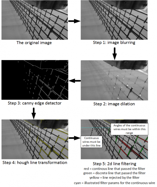
The goal of the mesh detector is to find two wires right beneath the welding tool head where new wires get inserted during the building process. We need to detect two wires because in order to form a full pose we need at least 3 linearly independent points in 3D (one wire=line would only give us two 3D points). A wire is detected as a line in 3D using a tailor-made, problem specific stereo vision approach. First we detect lines in the each stereo vision image seperately:

- Image blurring: In order to get rid of noise, we blur the image using a normalized box filter. It would also be possible to use a Gaussian kernel to blur the
- Image dilation: Consider the original image. There are wires in the background that we are not interested in. Clearly, the wires in the background are farer away than the wires in the foreground which makes them appear smaller. This is why we use dilation, which makes objects with the same shape smaller. In our case, this will make the wires in the background disappear whereas the wires in the foreground will just become smaller and still be detectable as lines.
- Canny Edge detector: We use the well known Canny-Edge detector4) implemented in open-cv to find edges in the image. It is a preliminary for the next step.
- Hough line transformation: We use the probabilistic Hough transform 5) implemented in open-cv to detect the two side of the wire as lines.
- 2d line filtering: This step gets rid of lines that most probably do not belong to the wires we are trying to find. We define two filters: a) the wire must be under the welding clamps b) the wire must lie in a certain angle range. The filter parameters are chosen in such a way that it is highly unlikely for the filter to be discarding the wire we are looking for. The filter parameters are adjusted for the continuous and the discrete wire separately.
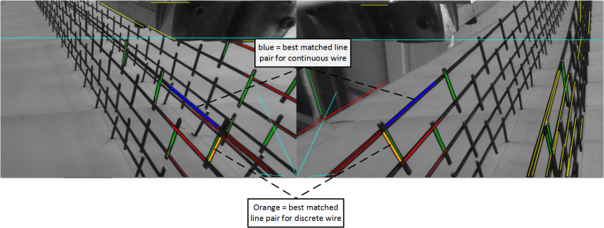
This step of the algorithm gives us a set of lines in each stereo vision pair. Since we have a computer model of the mesh mold we have an expected 3d position of the two wires we are looking for. Thus, the idea is to try out all combinations of lines found with the method described above, project them to 3d using epipolar geometry and try to find the two pairs that best matches our expected wire from the CAD model. To achieve that goal, we use a cost function that finds the best 3D line match.
 <latex> {\fontsize{12pt}\selectfont \textbf{Results} </latex>
The thesis has showed the development and implementation of a feature based robot pose estimation system and a tailor-made stereo vision approach to detect wires of the mesh mold. The presented concepts were integrated into the IF system environment using well-defined interfaces and were tested on real hardware with satisfying results. All code was tracked using a version management tool and was reviewed by the advisor. Beside some future work described below, the IF has been enhanced with a perception system that gets it a step closer to accurately and collision-free fabricate a wall on a real construction site.

