Sidebar
<latex>{\fontsize{16pt}\selectfont \textbf{Estimating Whole Body Impedance}} </latex>
<latex>{\fontsize{12pt}\selectfont \textbf{Pascale Meier}} </latex>
<latex>{\fontsize{10pt}\selectfont \textit{Semester Project ITET}} </latex>
<latex> {\fontsize{12pt}\selectfont \textbf{Abstract} </latex>
The stiffness of a human's joint depends strongly on its activity. Imagine someone drilling a whole, in this case its arm will be much stiffer rather than while writing an essay. Single joint impedance has already been investigated quite well but not the coupling of them. There are several reasons why the area of robotics is interested in this topic, on one hand if there is a direct interaction between a robot and a human, as this is the case in rehabilitation engineering, on the other hand to have a simplified model for control of autonomous robots. Therefore, one possibility to investigate that is to analyse the behaviour of a human's centre of mass (CoM) while applying an external perturbation.
<latex> {\fontsize{12pt}\selectfont \textbf{Experimental Design} </latex>
There were four test persons performing three different experiments. They were equipped with reflective markers and an IMU and perturbed with a stick with a force sensor on top of it.
<latex> \textbf{Experiment 1} </latex> The subject was instructed to stand on two legs whereas its feet were side by side and its arms next to its chest so that it behaved more like an inverted pendulum and to avoid occlusions of the hip markers. Hence, the subject was pushed from the side and from behind.
<latex> \textbf{Experiment 2} </latex> The subject was instructed to stand on one leg, first on the strong one and afterwards on the weak one. Its arms were next to its chest again. As before it was perturbed from the side and from behind.
<latex> \textbf{Experiment 3} </latex> The subject was instructed to stand on two legs again but this time it was holding a spoon filled with styropor balls whereas it was told to spill as few as possible. Like in the two other experiments the subject was pushed from the side and from behind and the arm that wasn't holding the spoon was next to its chest.
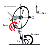
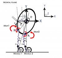
The used human body model was divided into a sagittal and a frontal plane:
Sagittal Plane Model:
$ m\ddot{z} = F_{z,proj} - F_{s}cos(\alpha) $
$ = F_{z,proj} - k_{leg}(l_0 - l)\dfrac{dz}{\sqrtdy_2_dz_2 $
$ m\ddot{y} = -F_g + F_{y,proj} + F_{s}sin(\alpha) $
$ ~ = -mg + F_{y,proj} + k_{leg}(l_0 - l)\dfrac{dy}{\sqrtdy_2_dz_2 $
$J\ddot{\phi} = -s_1F_{s} - M_{ankle} + M_{hip} +
dF_{y,proj}cos(\theta) - dF_{z,proj}sin(\theta)$
Frontal Plane Model:
$ m\ddot{x} = F_{z,proj} - F_{s1}cos(\alpha1) - F_{s2}cos(\alpha2)$
$ = F_{z,proj} - k_{leg_1}(l_{01} - l)\dfrac{dx_1}{\sqrtdy_1_2_dx_1_2 -k_{leg_2}(l_{02} - l)\dfrac{dx_2}{\sqrtdy_2_2_dx_2_2 $
$ m\ddot{y} = -F_g + F_{y,proj} + F_{s1}sin(\alpha1) + F_{s2}sin(\alpha2)$
$ ~ = -mg + F_{y,proj} + k_{leg_1}(l_{01} - l)\dfrac{dy_1}{\sqrtdy_1_2_dx_1_2 +k_{leg_2}(l_{02} - l)\dfrac{dy_2}{\sqrtdy_2_2_dx_2_2 $
$J\ddot{\phi} = s_1F{s_1} + s_2F{s_2}+ M_{ankle1} + M_{ankle2} - M_{hip1} + M_{hip2} - d_1F_{y,proj}cos(\theta) + d_1F_{z,proj}sin(\theta)$
Apart from the third experiment there was no instruction about how the test person should react to an external perturbation. Duet to the fact that after ca. 50ms a human's reflexes take effect and after 150ms more a human is conscious about what is happening, mainly the range of 0ms to 200ms was of interest in order to investigate how the stiffness behaved.
<latex> {\fontsize{12pt}\selectfont \textbf{Methods} </latex>
As equipment an IMU (from Microstrain), a Motion Capture System called Optitrack and a force sensor called Optoforce were used.
The purpose of the IMU was on one hand to measure the acceleration of the human body, and on the other hand to correlate the data sets since the IMU and the force sensor were connected to one computer and the Optitrack to another one.
The Motion Capture System was used to track the movements of the test persons whereas mainly the markers on the trunk and at the ankles were of interest. The trunk had been divided into an upper and a lower rigid body whereas it was assumed that the CoM was calculated as follows: $ r_{CoM} = \frac{m_{upper}r_{upper} + m_{lower}r_{lower}}{m_{upper} + m_{lower}} $, under the assumption that the upper and lower rigid body were of same weight. Furthermore, since there is always the gravitational acceleration in the data of the IMU, this acceleration was subtracted by tracking the orientation of the IMU in the Optitrack coordinate frame.
The force sensor was a three axis force sensor that had to be calibrated first, it was on top of a stick that was used to perturb the test persons.
<latex> {\fontsize{12pt}\selectfont \textbf{Results} </latex>
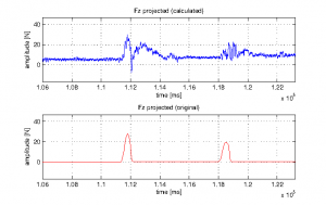
In a first step the sagittal plane was investigated with a human standing on two legs. In order to analyse how the stiffness behaved, windows of different sizes were used (in the range of 1ms to 800ms) whereas the unknown parameters (stiffness and relaxed lengths) were estimated using linear regression. It turned out that the stiffness were negative in a range were reflexes still didn't take effect, what was not a very comprehensible result. Also changing the moment of inertia and adding a damper didn't change the values significantly. Since the analysed test person seemed taking a step another test person (also standing on two legs) that behaved more like an inverted pendulum was taken. Furthermore, it was assumed that the main force appeared horizontally and that there was mainly an angle of 90 degrees between the z-axis and the ankle of the test person. Additionally, it was assumed that the pushed mass was not the mass of the subject but only the mass of its trunk. Hence, the unknown parameters were not only the stiffness and the relaxed lengths of the springs but also the mass. In order to check the stiffness results they were reinserted into the equations of motion to compare the calculated force values with the original ones. The stiffness still resulted in a negative values where it was supposed that no reflexes appeared but the reinserted force values did match the original ones not that bad for larger window sizes, also in a range outside the analysed one.
| Reinserted force values compared to the original ones, using parameters estimated for a Window Size of 800ms |
|---|
 |
<latex> {\fontsize{12pt}\selectfont \textbf{Conclusion \& Discussion} </latex>
There might be several reasons why the sagittal plane model didn't work the way as expected. On one hand there was almost no deflection into the y-axis on the other hand the angle between the the ankle and the z-axis was almost 90 degrees, therefore it made it very difficult to calculate meaningful values for the stiffness. Furthermore, regarding the second test person, a negative acceleration was measured after the perturbation during the first few milliseconds. Since the test person was pushed at the tail bone and the IMU was located a little bit further above it might be that there was a backspin. Therefore, the trunk can't be simplified probably just to one rigid body, hence another more sophisticated model would be necessary.


