Sidebar
<latex>{\fontsize{16pt}\selectfont \textbf{Mechanical Design and Control of a High-Performance Treadmill for the Quadrupedal Robot HyQ}} </latex>
<latex>{\fontsize{12pt}\selectfont \textbf{Robert Bichsel}} </latex>
<latex>{\fontsize{10pt}\selectfont \textit{Semester Project RSC}} </latex>
<latex> {\fontsize{12pt}\selectfont \textbf{Abstract} </latex>
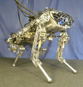 The aim of this project is the construction of a treadmill which serves as a test bench for the hydraulic quadrupedal robot HyQ. This robot of 70 kg weight and with the ability to perform a vast variety of behaviors puts high demands to its test bench. First of all, the structure needs to be robust enough to support the high payload along with its dynamic effects. Secondly, it needs to be big enough to allow the robot to perform its behaviors (including sideways movement, fast accelerations and decelerations, etc.). And finally the drive of the treadmill has to be able to keep up with the dynamics of the robot, which means high peak speed and peak acceleration. Commercially available treadmills can’t fulfill these challenging requirements, which is why the customized approach was chosen.
An interesting aspect of the project is that the infrastructure readily available in the lab may be used. This includes a motion capture system which can be used to determine the position of the robot and can be used as an input for the controller. It also includes the hydraulic infrastructure, which provides the option of operating the treadmill hydraulically.
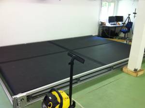
The result of the project is a 5m long and 3.2m wide treadmill with a 5kW hydraulic drive. It is operated via a PID controller in order to assure the required velocity.
<latex> {\fontsize{12pt}\selectfont \textbf{Requirements} </latex>
- Accelerated payload = 150 kg: Consisting of HyQ (70 kg) + optional on-board pump (35 kg) + margin
- Structural payload = 700 kg: 1) Consisting of Accelerated payload times 3 (estimated factor for dynamic impact, due to running and jumping) + 3 people on the treadmill (250kg).
- Max. velocity = 4 m/s: Estimated max. velocity of HyQ = 4 m/s
- Max. acceleration = 2 m/s2: Estimated max. acceleration of HyQ = 2 m/s2
- Length = 5 m: Due to estimated space required for operation at high speed, verified by the simulation.
- Width = 3.2 m: Due to ability of HyQ to perform sideways movements, constrained by dimensions of lab
- Height: minimal: Due to the low ceiling in the lab
- Reverse operation of treadmill: Ability of HyQ to walk backwards
<latex> {\fontsize{12pt}\selectfont \textbf{Simulation} </latex>
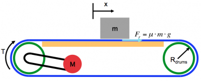
A model of the system as shown in the following figure is used to determine the basic parameters such as required torque, required speed and required power. The following assumptions were made:
- Constant mass
- No impact/perturbations due to robot gait
- No motor dynamics
- No friction in bearings
- No slip between belt and drums
- Losses in transmission can be neglected
With the help of Newton's law (rotational version)
\begin{equation} T=J\cdot&\alpha& \end{equation}
and given the requirements, the following values could be found:
| Rotational speed | = 51 rad/s = 490 rpm |
| Torque | = 95 N |
| Power | = 4.9 kW |
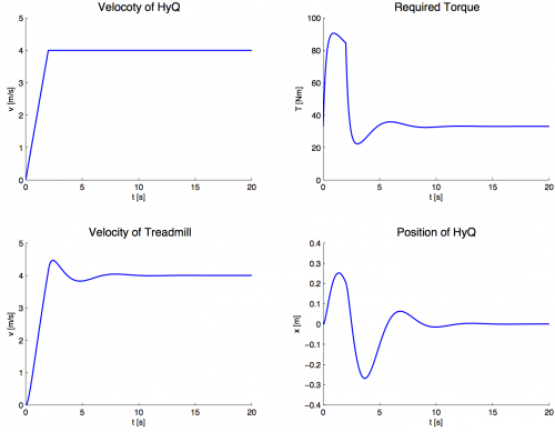
In order to verify these values, a Simulink model was run. The model furthermore allowed to estimate the parameters for the controller (such as gains), and observe the bahavior of the treadmill when operate by the controller. The controller was modeled by a simple PID-controller with the position as a control input (position control, position assumed to be known due to OptiTrack). The following figure shows the velocity of HyQ (given as an input, top left), the consequent torque (top right) and velocity (bottom left) of the treadmill, and finally the position of HyQ on the treadmill (bottom right).
<latex> {\fontsize{12pt}\selectfont \textbf{Mechanical Design} </latex>
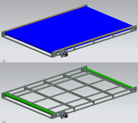
All the mechanical parts have to be designed so that they can withstand the forces and moments acting on them and generate the necessary performance. For every part, potential solutions were assessed and the best-suited one chosen and verified. In particular:
- As determined in the simulation, the motor has to deliver a performance of roughly 5 kW, at 490 rpm and 95 Nm. Furthermore, a favourable behavior at low speeds and a high efficiency are required. It was judged, that a hydraulic drive outperforms its electric brother. This is not only due to its better behavior at low speeds, but also due to the fact that the hydraulic infrastructure in the lab can be exploited.
- For the belt, it is crucial that the friction coefficient on the lower side is low, whereas the one on top is high. Furthermore it must withstand the pull at maximal acceleration in addition to the applied pretension.
- The frame is designed so that it is able to bear the load of the robot (impacts included) and the tension coming from the belt.
- The drums which guide the belt, and their corresponding axes have to support the belt pull. As the treadmill accelerates and decelerates periodically, a dynamic analysis was conducted.
- All the other parts, such as the chain and the chain wheels for the chain drive or the ball bearings for the axes, are chosen to suit the application in terms of forces, moments and longevity.
<latex> {\fontsize{12pt}\selectfont \textbf{Control Design} </latex>
A basic overview of the control system can be seen in the above figure. Two different control modes are set up: On one hand there is the position control with its position input from the motion capture system, and on the other hand there is the velocity control, which requires a velocity input. For both modes, the controller produces an output signal in order to run the treadmill motor at the required speed.
<latex> {\fontsize{12pt}\selectfont \textbf{Conclusion} </latex>
A well working test bench is of an utmost importance for a complex robot such as the HyQ. Being attached to an external pump through his umbilical cord (hoses and cables) and at a stage where his agility is still limited, time-efficient and successful experimentation depends to a big extent on the treadmill. The goal is, of course, to get off the treadmill and into rough terrain. However, this requires further research on gait control, navigation, perception, and so on. And until HyQ is ready to take the big leap out of the lab, this high performance treadmill will prove its performance on numerous occasions.
<latex> {\fontsize{12pt}\selectfont \textbf{Future Work} </latex>
There is still some work to be done before the treadmill can take up its operation. First and foremost, the setup of the control system has to be finalized. This includes connecting the sensors to the Raspberry Pi computer and making sure that all the data is available. Furthermore, the control algorithms have to be implemented in the Raspberry Pi. Then, with the control system in place, the treadmill needs to be put into service and tested. Eventually some of the parameters in the control algorithm will have to be changed in order to assure good and smooth operation. Once all of this work is done, the treadmill is ready to facilitate the various behaviors of HyQ and the experiments can begin.

