Sidebar
<latex>{\fontsize{16pt}\selectfont \textbf{Design of a Real-Time Control System for an In-Situ Fabrication Robot}} </latex>
<latex>{\fontsize{12pt}\selectfont \textbf{[Rosali Pyun]}} </latex>
<latex>{\fontsize{10pt}\selectfont \textit{[Master Project ME]}} </latex>
<latex> {\fontsize{12pt}\selectfont \textbf{Abstract} </latex>
An in-situ fabrication robot, DimRob, is being developed, in cooperation between the Digital Fabrication Lab of the ETH architecture school and the ADRL, to autonomously perform precise building tasks directly on construction sites. It consists of an industrial robotic arm mounted on a hydraulically driven tracked mobile base. In this project, the controller system of DimRob was designed and a preliminary software was implemented in order to make the robot fully autonomous. We equipped the robot with a suitable computer and data acquisition system to handle the low-level sensing and actuation. The low-level controller operates in Linux with a real-time patch called Xenomai. Analogy, the data acquisition card driver provided by Xenomai, has been successfully implemented to provide the functionality of the data acquisition in real-time. The real-time capability of the control system has been demonstrated through bench-top experiments.
<latex> {\fontsize{12pt}\selectfont \textbf{Status and Challenges} </latex>
| DimRob at 2011 Scientifica Exhibition 1) | |
|---|---|
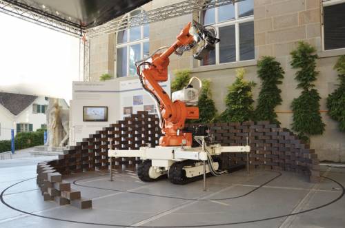 | A previous version of DimRob was capable of executing construction tasks while recognizing its position, surroundings as well as building materials, but it could perform the given task only at a stationary position with its four legs as a stabilizer 2). The operation procedure of DimRob was divided in two major stages: driving the robot to the designated location manually and then operating the arm autonomously. Our optimal goal was to re-design the robot to localize and navigate autonomously in construction sites and perform tasks with the arm simultaneously cooperating with the base in motion. |
The required modifications for the subsystems of the robot:
- Re-design the hydraulic system with proper sensors and actuators to be controlled electronically.
- Power the mobile base and the robot arm with on-board power electronics system.
- Integrate the robot arm controller to the robot.
- Design a control system hardware and implement to realize the driving in automatic mode
The design requirements for the control system:
- Expandability of the expansion both in hardware and software system
- IP 65 protection of the electronic components
- Real-time control of the hydraulic sensors and actuators
<latex> {\fontsize{12pt}\selectfont \textbf{Control System Hardware} </latex>
The control system architecture is designed based on the modifications in the hydraulic and the power electronics system. The task of the control system is divided into two controller systems: the low-level controller (LC) and the high-level controller (HC). The fundamental tasks of the LC with a data acquisition card (DAQ card) are the control of low-level sensor and actuator signals for the hydraulics. The LC operates in hard real-time since a delayed signal may cause failure in control of the hydraulic system. The HC handles a high computational control with control of the high-level sensors for navigation and localization. The computers should be powered by DC power supply units to use the DC power from the battery, the on-board power electronics system. In case of emergency, wired and wireless emergency stop (E-stop) disconnects the power from the main actuators of the system: the robot arm and the electric motor.
<latex> {\fontsize{12pt}\selectfont \textbf{Xenomai: Real-Time Operating System} </latex>
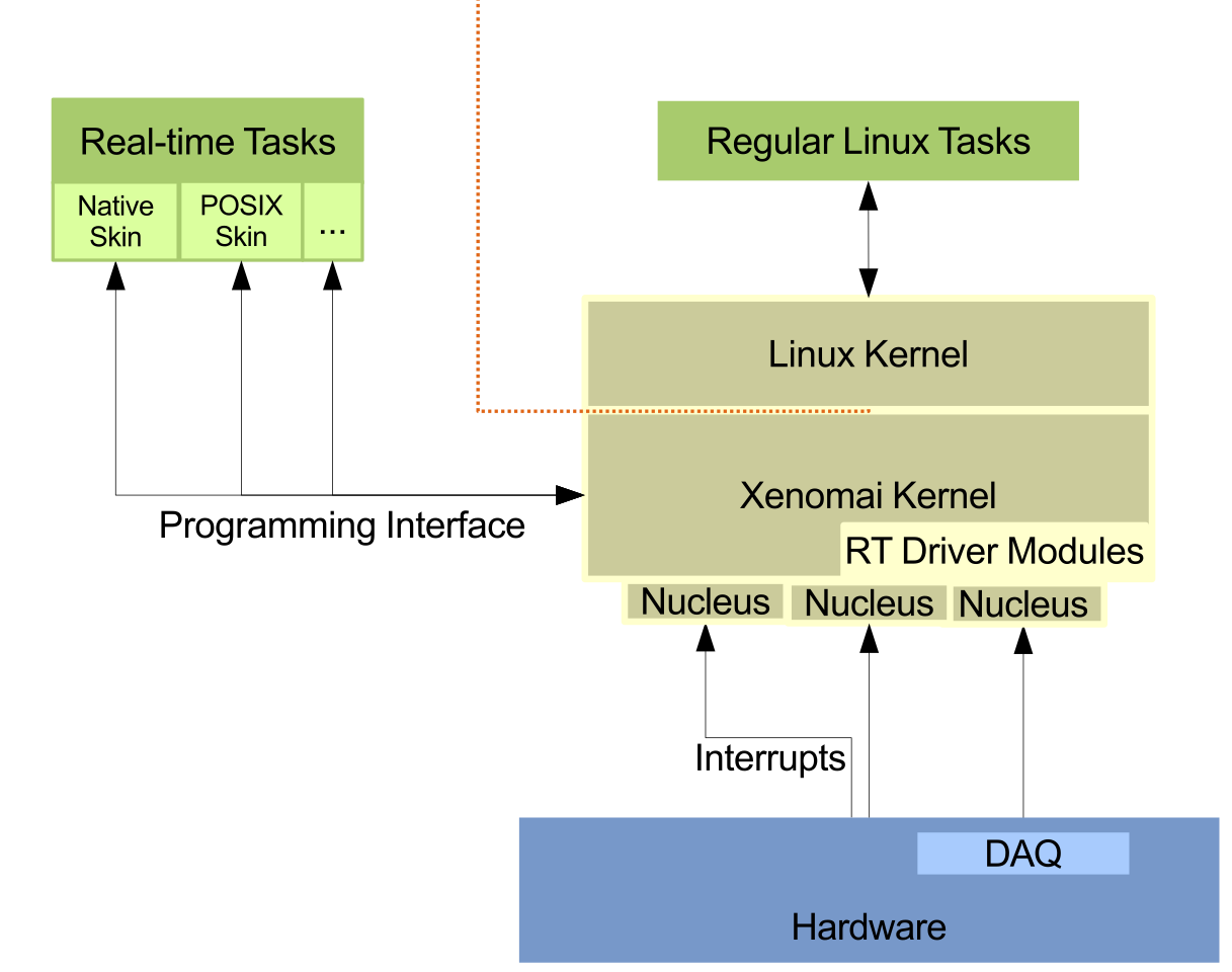
Xenomai, a real-time patch integrated into the Linux kernel, was chosen as a Real-Time Operating System for the LC in hard real-time, which meets deadlines in a deterministic way. The figure shows a simplified architecture of Xenomai patched Linux system.
Xenomai kernel sits below Linux kernel and acquires all the interrupts coming from the hardware including the interrupts for regular Linux tasks. Real-time tasks are handled first, and the intercepted interrupts for the regular Linux tasks are passed to Linux kernel afterwards.
<latex> {\fontsize{12pt}\selectfont \textbf{Software Architecture} </latex>
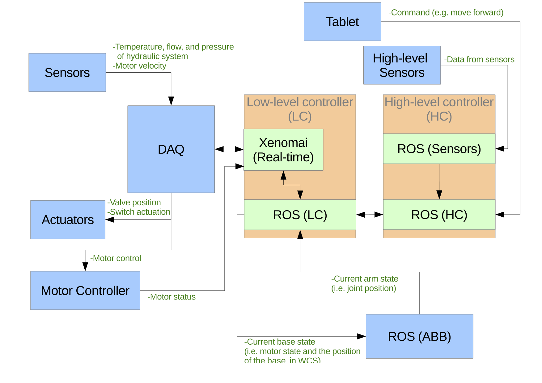 The software architecture of DimRob is shown in the figure. The main program in the LC runs two tasks simultaneously: a real-time task with Xenomai and a non-real time task with Robot Operating System (ROS). Xenomai provides a pre-compiled device driver called Analogy, a data acquisition device driver in real-time. Analogy provides the data acquisition functionalities needed for our system: load and configure the device and read and write analog and digital signals. The low-level signals for the hydraulic sensors and actuators are handled in real-time via Analogy, and the acquired data is transmitted via ROS. ROS, a middleware, was implemented as a common ground for the communication interface between the control modules such as the LC, the HC, and the ABB arm controller
During the project, the implementation of the preliminary software for the LC was successfully completed with the operating system Ubuntu 12.04 with Xenomai 2.6.3 patch.
<latex> {\fontsize{12pt}\selectfont \textbf{The Bench-Top Experiment} </latex>
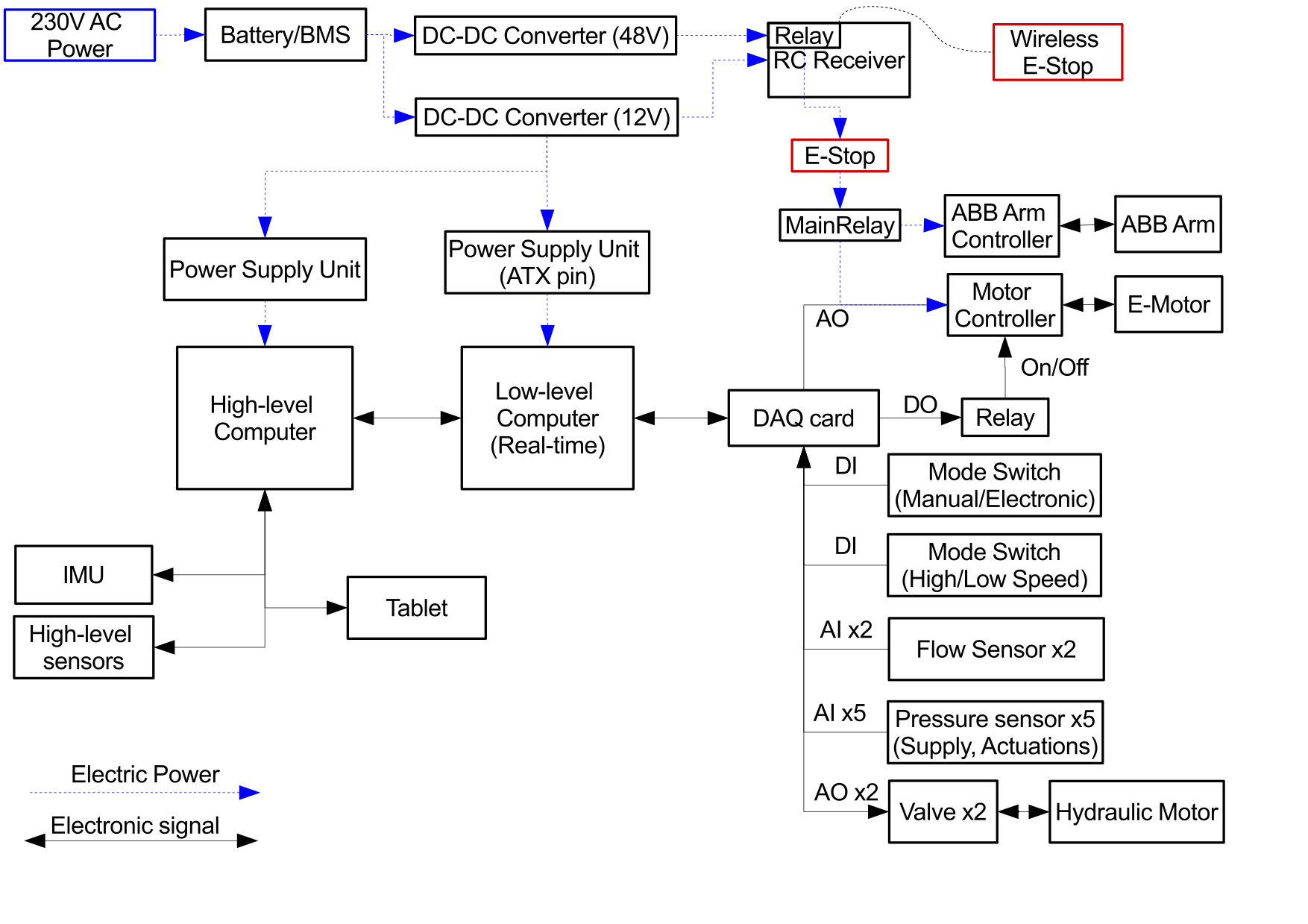
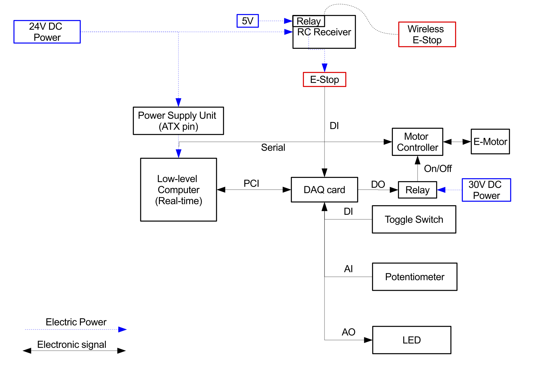 The bench-top experiment was designed to examine the implementation of the software and also as a proof of concept for future integration of the hydraulic system. Not all hardware was available to operate DimRob at the moment due to the modification in the system. Therefore, the experiment was designed with an electric motor, a motor controller, a wireless E-stop, a wired E-stop, an LED, a potentiometer and a toggle switch to test the basic functionalities of the DAQ system. The system architecture of the bench-top experiment is shown in the figure. The figure represents what has been realized at the end of the project.
The software was implemented with a real-time task and a non-real time task as described in the software architecture. The commands for the DAQ card were handled in the real-time task with a frequency of 200 Hz, an expected frequency for the robot, and the ROS publisher and the command for the motor controller were implemented in the non-real time task at 20 Hz.
First, the E-stop status is checked, and if any of E-stops is pressed, the motor and the LED was turned off. If the E-stop system is not enabled, the potentiometer value is acquired and stored into a variable. Afterwards, the toggle switch status is checked. Depending on the toggle switch status, two different procedures are executed. If the switch is on, the brightness of the LED is adjusted by generating an analog output signal proportional to the potentiometer value acquired in the previous step. If the switch is turned off, the desired motor speed, which is proportional to the potentiometer value, is passed to the non-real time task to send a command to the motor controller. In the non-real time task, the requested motor command along with the timestamp are published via ROS. The global variables used between the real-time task and the non-real time task are protected by the mutex functionality.
<latex> {\fontsize{12pt}\selectfont \textbf{Conclusion} </latex>
The in-situ fabrication robot, DimRob, required significant modifications and improvements in the hydraulics, the power electronics and the control systems to make the robot fully autonomous. In this project, the control system for the robot was designed based on the modifications in other systems. Most of the DAQ card related functionalities in real-time were realized for the LC, and the bench-top experiment was successfully performed to demonstrate the feasibility of future integration of the hydraulic sensors and actuators.
<latex> {\fontsize{12pt}\selectfont \textbf{Future Work} </latex>
- Integration of the LC into hydraulics and power electronics system.
- Installation of the controller on the robot.
- Design of the user-interface system and the high-level controller.
- Implementation of counter, Serial communication, Ethernet network in real-time.
- Realization of the communication between the ABB arm controller and the LC.
- Implementation and development of high-level control algorithms for autonomous navigation in construction environments.
Page Tools
