Sidebar
Table of Contents
Abstract
In this project, we design a mobile manipulator with four wheel differential driven mobile base and 6 DoF hydraulic arm to be used in on-site building construction tasks, and we evaluate the feasibility of the inverse dynamics controller in the constraint consistent dynamics. Firstly, the Gazebo simulation of the mobile base and the hydraulic arm is prepared. Then the rigid body dynamics of the robot are modelled using simplified base actuation dynamics. The rigid dynamics are projected to the constraint consistent manifold. Finally, the inverse dynamic algorithms are implemented in the configuration space and the task space, and their performance are evaluated via experiments in the Gazebo simulations.
Modeling
Base Actuation
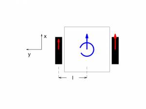
In order to avoid overly complicated friction model, we excluded the dynamics of the wheel in our design and we used a simplified base model with two wheels for base dynamics.
After these simplifications, we need following assumptions to characterise relation between base actuation torques and wheel torques.
- Wheels are always in contact with the ground
- Wheels apply force on the base only in x and z direction, the lateral
forces and moments are ignored.
- No motion in z direction of the base fixed frame
- The CoM of the robot does not change during the motion.
By using these assumptions, we can calculate the torque commands for the right and the left wheels from torque around z-axis and force in x axis via following equation,
<latex> \begin{equation*}
\begin{bmatrix}
	\tau_{r} \\
	\tau_{l}
\end{bmatrix}= \begin{bmatrix}
	r/(2l) & r/2 \\
	-r/(2l) & r/2
\end{bmatrix}\begin{bmatrix}
	\tau_\phi \\
	F_x
\end{bmatrix}
\label{wheel_torques}
\end{equation}
</latex>
where $r$ is the radius of the wheels and $l$ is the distance between the wheels and the CoM of the base. After calculating the wheel torques, it is integrated over time to obtain angular velocity command as in the below equation. Note that this integration assumes, that there isn't any sliding friction at the ground contact.
<latex> \begin{equation*}
w^i(t+\Delta t) = (\tau-b_{w} w^i(t))\Delta t /I_{w}
\label{wheel_vel}
\end{equation} </latex>
$w^i$ is the angular velocities of $i^{th}$ wheel,and $I_w$ and $b_w$ are the estimates of the inertia and the damping of the wheels. The estimation of the damping of the wheel is not possible without an accurate model of the friction dynamics, therefore it is also tuned with controller gains.
Rigid Body Dynamics
The mobile base is modelled as a floating body in the base fixed coordinate frame. Thus, the configurations, which fully describe the state of the robot, are composed of the pose of the base $\Bf x_B\in SE(3)$ and the joint angles of the arm $q_A\in R^6$
<latex> \begin{equation*}
q = \begin{bmatrix}\Bf x_B \\ q_A \end{bmatrix}
\end{equation} </latex>
With $q$ as the state of the robot, below equation shows the rigid body dynamics of the robot in the configuration space.
<latex> \begin{equation*}
M(q)\ddot{q}+H(q,\dot{q})=S^T\tau_a+J_c^T\tau_{c}
\end{equation} </latex>
The left handside terms $M\in R^{12\times12}$ and $H\in R^{12}$ are respectively the inertia matrix, the sum of coriolis/centripetal and gravity forces. And the right handside terms $S\in R^{8\times12}$ and $J_c\in R^{4\times12}$ are respectively the selection matrix and the contact Jacobian. The actuation torque $\tau_a\in R^8$ is composed of the base actuation torque in z-axis, base actuation force in x-axis and 6 torque command for the joints of the arm. The contact force $\tau_c\in R^{4}$ represents the unknown moments and forces applied to the base by the ground through the wheels.
<latex> \begin{equation*}
\tau_a = \begin{bmatrix}
\tau_\phi & F_x & \tau_{arm}
 \end{bmatrix}^T \in\real^8
\end{equation} </latex>
The $6\times6$ identity matrix and the pair of ones in selection matrix respectively corresponds to the actuation of the arm joints and the base actuation in yaw and x direction. On the other hand, the left pair of ones in the contact Jabocian represents rotational constraints on the base around x-axis and y-axis, and the right pair of ones represents constraints on the linear motion in y and z direction which is parallel to assumptions on the base actuation.
<latex> \begin{gather*}
		S = \begin{pmatrix}
				\begin{matrix}
					0 & 0 & 1 & 0 & 0 & 0 \\
			   		0 & 0 & 0 & 1 & 0 & 0 \\
				\end{matrix} & 0_{2\times6} \\
				0_{6\times6} & I_{6\times6}
		    \end{pmatrix}
		\label{eqn:Selection} \\
		J_c = 	\begin{pmatrix}
					\begin{matrix}
						1 & 0 & 0 & 0 & 0 & 0 \\
				   		0 & 1 & 0 & 0 & 0 & 0 \\
				   		0 & 0 & 0 & 0 & 1 & 0 \\
				   		0 & 0 & 0 & 0 & 0 & 1 \\
					\end{matrix} & 0_{4\times6}
			    \end{pmatrix}
		\label{eqn:Contact_Jac}
	\end{gather}
</latex>
Constraint Consistent Dynamics
The constraint consistent dynamics are obtained by applying QR decomposition to the contact Jacobian.
<latex> \begin{equation*}
J_c^T=Q\begin{bmatrix}R\\0\end{bmatrix}^T
\end{equation} </latex>
$Q\in R^{12×12}$ is an orthogonal matrix (namely $Q^TQ=I$), and $R\in R^{4×4}$ is an upper triangular matrix. Because of the constant contact Jacobian, these matrices can be calculated offline in our case. Then substituting $Q\times R$ into rigid body dynamics yields two orthogonal dynamics described below.
<latex> \begin{gather*}
S_cQ^T[M(q)\ddot{q}+H(q,\dot{q})]=S_cQ^TS^T\tau+R\tau_c\\
S_uQ^T[M(q)\ddot{q}+H(q,\dot{q})]=S_uQ^TS^T\tau
\end{gather} </latex>
$S_u=[0_{8×4} , I_{8×8}]$ and $S_c=[I_{8×4} , 0_{8×8}]$ are selecting the upper and the lower part of the rigid body dynamics. Second equation doesn't depend on the unknown contact forces and represents the constraint consistent dynamics on which we build our controllers.
Inverse Dynamics Controllers
We implemented inverse dynamic controllers, which generate torque signals for the base and the arm joints to reach given desired positions and velocities of the end-effector. Ultimately, we would like to have a task space controller for the mobile manipulator. However, as a first step, we implemented inverse dynamic controller in the configuration space under the constraint consistent dynamics. Therewith end-effector position and velocity can be controlled by inputing trajectories of the joint angles and the base position.
In the Configuration Space
We implement acceleration based inverse dynamic controller. The acceleration reference is set to summation of desired acceleration and PID terms for position and velocity tracking.
<latex> \begin{equation*}
\ddot{q}_{ref} = \ddot{q}_{des} + K_p( q_{des}- q) + K_d(\dot{q}_{des}-\dot{q}) + K_i(\int(q_{des}-q)dt )
\end{equation} </latex>
where $K_p,K_d,K_i\in\real^{12\times12}$ are PID gains. It is important to note that the state of the robot is in base fixed coordinate frame and it is assumed that we have perfect information of the state of the robot.
Then the constraint consistent control input is obtained by re-organizing rigid body dynamics.
<latex> \begin{equation}
\tau = P [\hat{M}(q)\ddot{q}_{ref}+\hat{H}(q,\dot{q})]
\end{equation} </latex>
$P = (S_uQ^TS^T)^{-1} S_uQ^T$ and $\hat{M}$ and $\hat{H}$ are the estimates of the $M$ and $H$ in real dynamics. The errors in different elements of $q$ are affecting each other through the inertia matrix. While selecting gain matrices, we choose the diagonal matrices for sake of simplicity and diagonal terms corresponding to constrained directions are set to zero.
In the Task Space
To characterize the relation between configuration space and task space, we need to calculate $6\times12$ dimensional end-effector Jacobian matrix with respect to world frame.
<latex> \begin{equation}
J_E = 	\begin{bmatrix}
	\begin{matrix}
		R_{WB} & 0 \\
		R_{WB}[\Bf r_{BE}]^T_\times & R_{WB}
	\end{matrix}
	&
	\begin{bmatrix}
		R_{WB} & 0 \\
		0 & R_{WB}
	\end{bmatrix}  J_{BE}
\end{bmatrix}
\end{equation} </latex>
where $R_{WB}$ is the $3\times3$ rotation matrix between world and base frame, $\Bf r_BE$ is the position of the end-effector with respect to CoM of the base and $J_{BE}$ is $6\times6$ Jacobian matrix describing the relative motion of the end-effector with respect to the mobile base. Then the velocities of the end-effector are related to the velocities of the base and the joints as in the following equation,
<latex> \begin{equation}
 \Wf \dot{x}_E =\begin{bmatrix} \Wf  w_E \\\Wf v_E \end{bmatrix}
 = J_E\begin{bmatrix} \Bf  w_B \\\Bf v_B\\ \dot{q}_{A} \end{bmatrix}  =J_E\dot{q}
\end{equation} </latex>
where $w_E,v_E,w_B,v_B$ are the angular and the linear velocities of the end-effector and the base. The end effector velocities are expressed in world frame, whereas the base velocities are expressed in the base frame.
The time derivative of the above equation give us the acceleration of the end-effector in terms of the acceleration of the state, time derivative of the end-effector Jacobian and velocities of the state.
<latex> \begin{equation}
\Wf \ddot{x}_E =J_E\ddot{q} +\dot{J}_E\dot{q}
\end{equation} </latex>
Re-organizing this equation yields the acceleration reference in the configuration space as a function of accelaration reference in the task space.
<latex> \begin{equation*}
\ddot{q}_{ref} = J_E^\dag(\ddot{x}_{E,ref}-\dot{J}_E\dot{q})
\end{equation} </latex>
$J_E^\dag=M^{-1}J^T_E(J_EM^{-1}J^T_E)^{-1}$ is the inertia-weigthed psuedo-inverse rather than Moorse's psuedo-inverse, so that the motion in the task space is reflected to the configuration space inversely proportional to the inertias of the joints and base.
The acceleration reference in the task space is composed of desired acceleration plus PID controller with state feedback \footnote{The difference in desired orientation and the current orientation is calculated in the tangent space} as in the following equation.
<latex> \begin{equation*}
\ddot{x}_{E,ref} = \Wf\ddot{x}_{E,des} + PID(\Wf x_E,\Wf{x}_{E,des},\Wf\dot{x}_{E,des})
\end{equation} </latex>
An important part of the task space controller is the handling of redundancies. In the configuration space, we have 12 DoF and in task space only 6, which means that there will be redundant configurations throughout the motion and a null space controller is required resolve this problem. We used the following null space controller.
<latex> \begin{equation*}
N = - K_{q,d}\dot{q}-K_{q,p}(q-q_{nom})
\end{equation} </latex>
The first term is damping term for the configuration space, the second terms is designed to push joints to their nominal positions where they operate far from the joint limits and the singularities.
Moreover, the null space controller is applied to system in two different ways. The first approach is with pre-multiplication of the inertia matrix. Namely, the null space controller is placed in the acceleration reference of the configuration space. This way, the dynamic couplings also affect null space controller. However, this leads to an extra difficulty while tuning the null space gains.
<latex> \begin{gather*}
\tau = P[M(q)\ddot{q}_{ref}+H(q,\dot{q})]
\ddot{q}_{ref} = J_E^\dag(\ddot{x}_{E,ref}-\dot{J}_E\dot{q})+(I-J^\dag J) N
\end{gather} </latex>
The second approach is without pre-multiplication of the inertia matrix. Null space controller is added next to the inverse dynamic controller and then the dynamics are projected to the constraint consistent manifold.
<latex> \begin{gather*}
\tau = P[M(q)\ddot{q}_{ref}+H(q,\dot{q})+(I-J^\dag J) N]
\ddot{q}_{ref} = J_E^\dag(\ddot{x}_{E,ref}-\dot{J}_E\dot{q})
\end{gather} </latex>
Although, it is easier to tune gains for the controller without pre-multiplication than for the controller with pre-multiplication, it is still a challenging task.
Evaluation
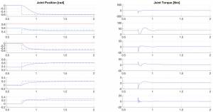
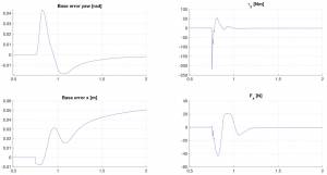
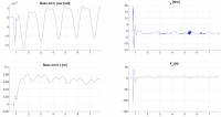
In order to evaluate performance of the inverse dynamic controller in configuration space, we prepared two different experiments in the Gazebo simulation. In the first experiment, step signals are applied to the arm joints, while the base is kept stationary. Then joint positions and torques,base position errors and base actuation torques are plotted.
The results of the first experiment shows that arm joints reach desired positions within one second and then, by the help of integral terms, they slowly compansate the errors which arise from dynamic couplings and modeling errors. Meanwhile, base agressively reacts to the motion of the arm in the first 2 seconds of the simulations. The initial rotation of the base is due to the jerk of the arm against which controller applies a sharp torque command to the base. On the other hand, the small motion of the base in x-direction is due to the integration of the wheels torques. It is mentioned in the base actuation chapter that integration of the wheels torques a technique which is meant to be used in slowly varying signals. After the initial displacement in x-direction,the base slowly recovers its position.
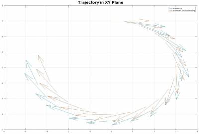
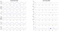
In the second experiment, a circular trajectory is given to the controller as in figure. The trajectory is composed of the time varying positions in XY plane and headings. And to observe the effect of the arm motion to the base sinusoidal signals are sent to the arm joints.
The joints are following the sinusoidal signal with a small delay, which is enough to show feasibility of the controller. On the other side, the base rotational error oscilates with the frequency of the arm joints sinusoidal signal, which means arm motion can create enough force to overcome friction wheels.
The base can follow the circular trajectory with some accumulating error. The reason of this error can be seen in the plot of base position errors. After the first 3 seconds, the mean error of the base is around $0.25\times10^{-2}rad$ and over time this small error create significant deviation from desired path in the lateral direction. This behaviour is unavoidable for trajectory tracking. Nevertheless, a trajectory can be engineered for better tracking by slowing the motion of the base or by giving additional rotation for headings in each time step.
Conclusion
he simulation results suggest that by generating an appropriate trajectory for the base and the joint configuration the inverse dynamic controller in the configuration space can be used for controlling mobile manipulator. It is also observed that the robot is significant slipping in y-direction, which is contradicting with our non-slipping contact condition assumption. This problem can be solved by modeling the frictions between wheels and the ground in the future works.
Unfortunately, we couldn't obtain satisfactory performance from the inverse dynamic controller in the task space. Our robot is fully actuated in the configuration space with the constraints, however, the robot is redundant in the task space. Our null space controller applies damping to arm joints and pushes them to their nominal angular position. However, we only use damping terms, since there isn't a desirable nominal pose for the base. The absence of such nominal pose destabilises the null space controller and results in an unstable base motion. To tackle this problem, in the future works a second null space controller which handles internal forces of the robot can be added to the inverse dynamics controller.
Finally, before implementing these algorithms on the real setup, we also need a state estimator for the mobile manipulator. As it is mentioned before our controllers receives base positions and velocities from the Gazebo simulator. In real setup, the base position and velocities can be estimated by fusing the wheels velocities, arm joint angles and accelerometer data.
To sum up, the inverse dynamic controller in the configuration space is shown to be feasible in simulations, but, the task space controller should be improved to be obtain satisfactory performance.

