Sidebar
<latex>{\fontsize{16pt}\selectfont \textbf{Balance Control of an Exoskeleton}} </latex>
<latex>{\fontsize{12pt}\selectfont \textbf{Mathias Wild}} </latex>
<latex>{\fontsize{10pt}\selectfont \textit{Semester Project, RSC}} </latex>
<latex> {\fontsize{12pt}\selectfont \textbf{Abstract} </latex>
Wearable robotics and exoskeletons in particular show great promise to help humans in rehabilitation or challenging work conditions. Currently, the balance of the exoskeleton and human are left entirely to the user. To improve safety and robustness of these devices, it would be preferable to delegate the balance task to the robot, especially if the user is for some reason unable to perform it. On that track, this project aims to implement state-of-the-art balance control on a simulated bipedal robot with finite sized feet. The selected approach is capture point based control to regain stability after large perturbations. This is complemented with null space control of the centre of gravity to maintain posture and stability for smaller perturbations inside the contact constraints. The algorithm successfully rejects smaller perturbations using the null space control in simulation, but fails to take the required step for capture point based control without losing balance for larger disturbances.
<latex> {\fontsize{12pt}\selectfont \textbf{Capture Point} </latex>

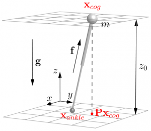
The capture point based balance strategies make use of a very simple model. A capture point is a point on the ground where a robot can step to in order to come to a complete stop.1) Finding such a point considering the dynamics of a complex bipedal robot could be very difficult. Luckily, that is not necessary. Capture point based balance strategies are essentially an extension of the Linear Inverted Pendulum Model. This model greatly simplifies the capture point calculation. With energy considerations we can find the instantaneous capture point. If the robot were to place its foot on this point instantaneously it would bring the system to a stop. It is calculated by
\begin{equation*}
\mathbf{x}_{ic} &= \mathbf{P}\mathbf{x}_{cog} +\frac{\dot{\mathbf{x}}_{cog}}{\omega_0}
\end{equation*}
where $\mathbf{x}_{ic}$ is the instantaneous capture point, $\mathbf{P}$ the ground projection matrix, $\mathbf{x}_{cog}$ and $\dot{\mathbf{x}}_{cog}$ the centre of gravity position and velocity respectively, and $\omega_0 = \sqrt{\frac{g}{z_0}}$ the reciprocal of the time constant of the inverted pendulum. No robot is able to move its feet to any location instantaneously, however, this capture point still provides valuable information about the stability of a complex system. While it is inside the area of support, the system can be recaptured by moving the centre of pressure on the instantaneous capture point, without taking a step. If it leaves the area of support, the instantaneous capture point can tell us where to step, especially if the dynamics of the capture point are considered also.
<latex> {\fontsize{12pt}\selectfont \textbf{Nullspace Control} </latex>
Mobile autonomous robots need to be able to cope with an unstructured environment while performing multiple tasks simultaneously. These tasks may conflict with one another, requiring a relative importance to be assigned to them. One solution to this problem is null space control.2) Consider a generic example: task variable $\mathbf{\sigma} \in \mathbb{R}^m$ is to be executed by a system with the configuration vector $\mathbf{p} \in \mathbb{R}^n$, which are connected by $\mathbf{\sigma} = f(\mathbf{p})$, such that
\begin{equation*} \mathbf{\dot{\sigma}} = \frac{\partial f\left( \mathbf{p} \right)}{\partial \mathbf{p}} \mathbf{\dot{p}} = \mathbf{J}\left( \mathbf{p} \right) \mathbf{\dot{p}} \end{equation*}
where $\mathbf{J} \in \mathbb{R}^{m\times n}$ is the configuration-dependent task Jacobian. For a series of tasks given in this form and ordered by priority, each configuration space action $\mathbf{\dot{p}_i}$ can be projected into the null space of the higher priority task using the Jacobians and added up to form a single command. Considering three tasks, where 1 has the highest priority, this yields
\begin{equation*} \mathbf{\dot{p}_{d}} = \mathbf{\dot{p}_1} + \left( \mathbf{I}-\mathbf{J}_1^\dagger \mathbf{J}_1\right) \left(\mathbf{\dot{p}_{2}} + \left( \mathbf{I}-\mathbf{J}_2^\dagger \mathbf{J}_2\right) \mathbf{\dot{p}_3} \right) \end{equation*}
where $\left( \mathbf{I}-\mathbf{J}_i^\dagger \mathbf{J}_i\right)$ is the projection into the null space of task $i$ and $\mathbf{J}^\dagger =\mathbf{J}^\intercal \left( \mathbf{JJ}^\intercal \right)^{-1}$ is the Moore-Penrose pseudoinverse. $\mathbf{\dot{p}_{d}}$ is the resulting desired configuration space command. This ensures that lower priority tasks only operate in the null space of the tasks with higher priority, i.e. they do not interfere with their execution. As a consequence, there is no guarantee that lower priority tasks will be executed.
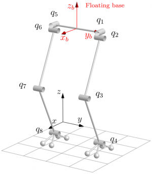
This concept can be applied to floating base legged robots.3) However, the task Jacobians have to be considered carefully. For the control task, we want to move the centre of gravity without moving the feet. Usually, the Jacobians of the end effectors, i.e. feet, are given relative to the floating base. For the considered case, the null space of the task of not moving the feet would be empty, as the reference system is the floating base. To fully account for the floating base, one has to extend the configuration space with the floating base position and orientation, $\tilde{\mathbf{q}} = \left[\mathbf{q}^\intercal \quad \mathbf{x_b}^\intercal \right]^\intercal$ with $\mathbf{q} \in \mathbb{R}^8$ and $\mathbf{x_b} \in \mathbb{R}^6$. With this we can now formulate the task Jacobians for the extended configuration space as \begin{equation*} \mathbf{\dot{x}_e} = \left[ \mathbf{J_q} \quad \mathbf{J_b} \right] \mathbf{\dot{\tilde{q}}} = \mathbf{\tilde{J}} \mathbf{\dot{\tilde{q}}} \end{equation*}
where $\mathbf{J_q} \in \mathbb{R}^{6 \times 8}$ maps the robot joint velocities to end effector velocities, relative to the base, and $\mathbf{J_b} \in \mathbb{R}^{6 \times 6}$ maps the base velocities to the end effector velocities, all displayed in the inertial frame. With that we have found the task Jacobian, and its null space is not empty. What is more, the null space projection can not only be applied to joint velocities, but to joint torques directly as well. This means that torques projected into the null space of a task or constraints, i.e. the feet do not move, do not generate any motion that would violate these constraints. Thus, it is possible to apply a simple PD control law to the CoG position to generate a virtual force to move the CoG, map this force into desired joint torques using the CoG extended Jacobian and project these torques into the constraint null space.
<latex> {\fontsize{12pt}\selectfont \textbf{Results} </latex>
 The resulting control algorithm was implemented in C++ on the SL simulation software.
The simulation was subjected to a set of perturbation cases.
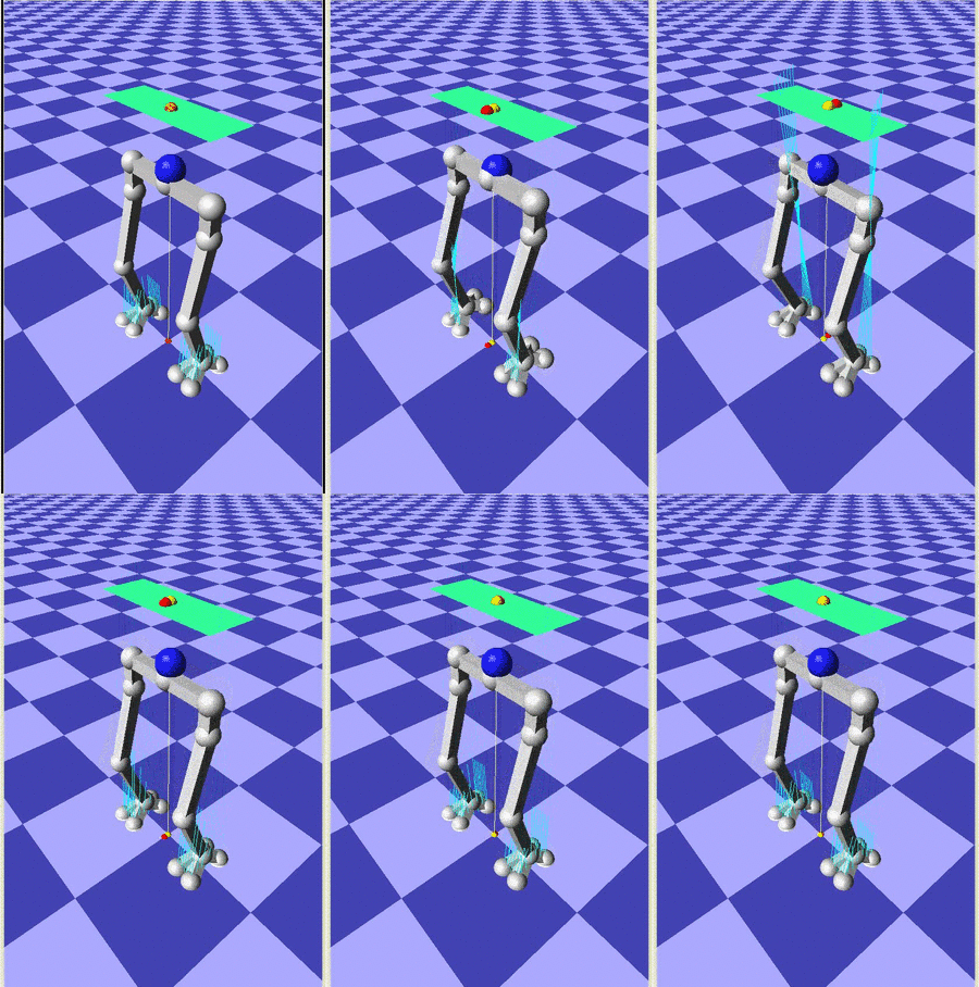
Anterior perturbations are rejected by the null space CoG control, seen in the animation shown here.
The perturbation is 1 kN over 100 ms, with a robot mass of 113 kg.
Lateral perturbations of the same strength are rejected also, however, since there is no corresponding degree of freedom at the ankle, the oscillatory behaviour takes much longer to dissipate.
In none of the cases mentioned above, the capture point left the area of support.
As such, only the null space controller was used to reject the perturbation.
If the perturbation was increased further, i.e. longer duration for anterior perturbation or superposition of lateral and anterior perturbations of the same magnitude, the capture point left the area of support, causing the robot to initiate a step towards the capture point.
Unfortunately, the stepping of the robot was itself not stable enough.
Because of that, the step caused the robot to fall.
<latex> {\fontsize{12pt}\selectfont \textbf{Conclusion} </latex>
The null space based control law for small perturbations performed as expected, even though the control parameters have not been optimised. Rejecting relatively large perturbations up to 1 kN applied to the hip over 100 ms required large ankle torques, however. Such a reliance on one joint should be avoided in the future through a better torque distribution. The redistribution may be achieved by introducing a weighing matrix to the pseudoinverse computation, but it has not yet been explored in this project. Larger perturbations on the other hand could not be rejected, since the robot failed to take a step without losing balance. Probably the most promising solution approach is an inverse kinematics and inverse dynamics implementation that is also based on null space control, to bring everything under one framework and no longer rely on SL in that regard. Alternatively, different stance control algorithms could be explored to ensure stability during stepping.


